Eureka AIR delivers breakthrough ideas for toughest innovation challenges, trusted by R&D personnel around the world.

Operation verification method for verifying operations of a processor

a verification method and processor technology, applied in the direction of program control, computation using denominational number representation, instruments, etc., can solve the problems of increasing the period needed for debugging in the design and preproduction phases of the semiconductor device, the logic of the processor for realizing the increase in the performance level of the server computer has become complicated, and the performance level demanded of the server computer has increased

Inactive Publication Date: 2008-07-17
FUJITSU LTD
View PDF0 Cites 11 Cited by
  • Summary
  • Abstract
  • Description
  • Claims
  • Application Information

AI Technical Summary

Benefits of technology

[0014]According to the present invention, operation instructions and input operands are created by the program at random, and thereby it is not necessary to hold verification instruction queues, operands, or expectation values in a table format, and also the expectation value is created by an execution element other than the target execution element; accordingly, it is possible to create significant data patterns almost unlimitedly for the verification of the target execution element.

Problems solved by technology

In recent years, the performance level demanded of server computers has increased, and the logic in the processors for realizing the increase in the performance level of the server computers has become complicated.
As the logic has become complicated and the degrees of integration in the semiconductor devices have increased, the periods needed for debugging in the design and preproduction phases of the semiconductor devices are increasing.
Accordingly, to perform verification on the basis of a large number of data patterns requires an immense program size.
Also, even when a program having tables of an immense size is prepared, the size of the program is limited by the size of the logical simulation model or by the memory amount in an information processing device on which the logical simulation model is executed.
Accordingly, the size of the program has been limited.

Method used


Image

  • Operation verification method for verifying operations of a processor
  • Operation verification method for verifying operations of a processor
  • Operation verification method for verifying operations of a processor

Examples


Embodiment Construction

[0027]Hereinafter, embodiments of the present invention will be explained by referring to the drawings.

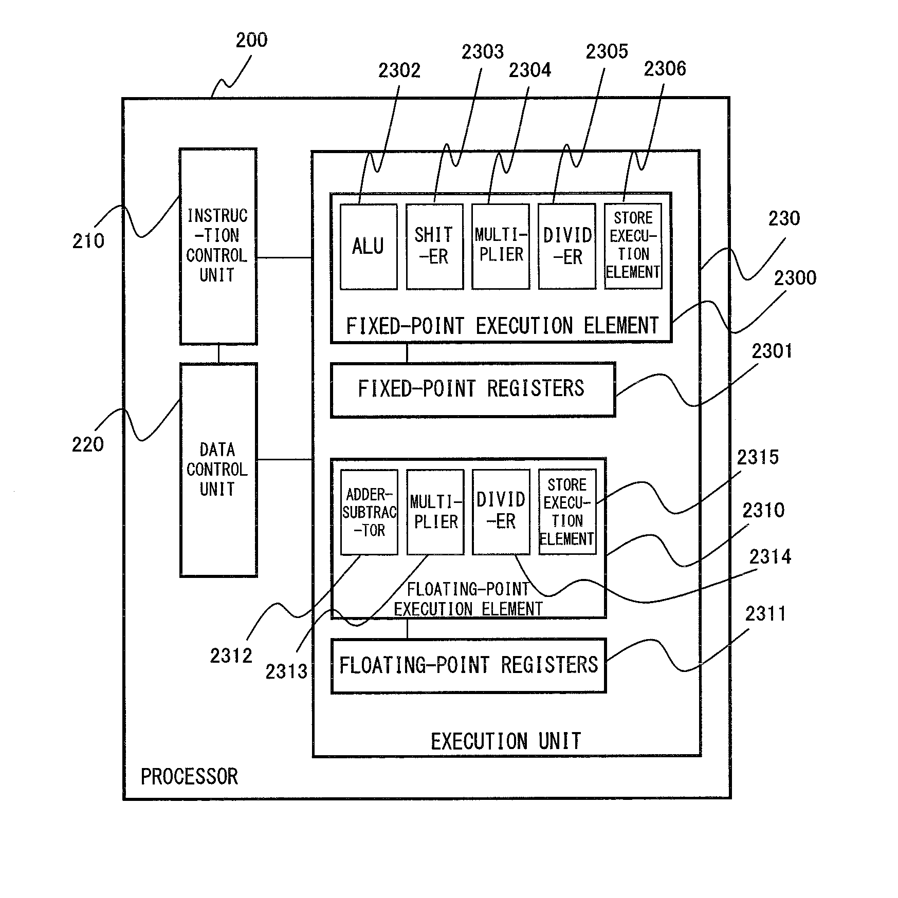
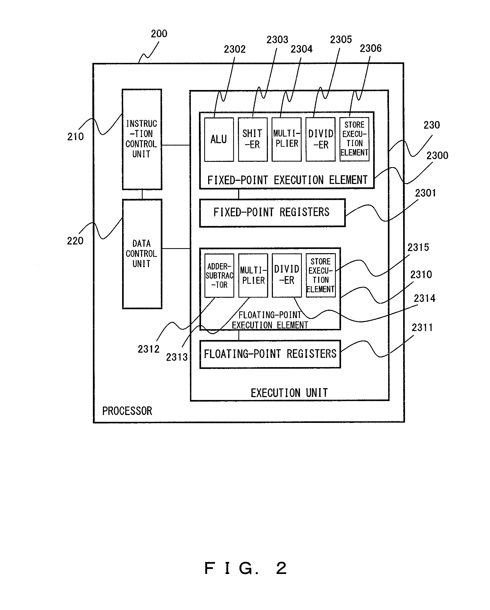
[0028]FIG. 2 is a block diagram showing a configuration of a processor according to an embodiment of the present invention. In FIG. 2, a processor 200 that is the target of the operation verification essentially includes an instruction control unit 210, a data control unit 220, and an execution unit 230. The instruction control unit 210 performs the bypass control of an instruction input and the operand caused by the interference of the register. The data control unit 220 sends to the execution unit 230 the data presented by the instruction control unit 210. The execution unit 230 performs execution on the data specified by the instruction control unit 210. The execution unit 230 includes thirty-two fixed-point registers 2301 each consisting of eight bytes, thirty-two floating-point registers 2311 each consisting of eight bytes, an ALU 2302, a shifter 2303, a multiplier 2304, a div...


PUM


Abstract

To verify an addition-function of a floating-point adder-subtractor in a processor, parameters such as the number of verification patterns of a verification program are set, a floating-point addition instruction to be verified is created, and operands used for this addition are created at random. The floating-point addition instruction thus created is emulated only by a fixed-point instruction and processed only by using the fixed-point execution element, thereby creating an expectation value. The floating-point addition instruction is computed by using the floating-point adder-subtractor to be verified, and the created expectation value is compared with the operation result. If they do not correspond to each other, the set number of operation patterns is checked. If the number has reached a prescribed value, the operation verification is terminated in the normal manner.

Description

CROSS REFERENCE TO RELATED APPLICATION[0001]This application is a continuation of the PCT application PCT / JP2005 / 023510 which was filed on Dec. 21, 2005.BACKGROUND OF THE INVENTION[0002]1. Field of the Invention[0003]The present invention relates to an operation verification method for verifying the operations of a processor, and particularly to a technique for verifying the operations of a processor by using a program for generating instructions and expectation values.[0004]2. Description of the Related Art[0005]In recent years, the performance level demanded of server computers has increased, and the logic in the processors for realizing the increase in the performance level of the server computers has become complicated. Also, the degrees of integration in the semiconductor devices have increased too. As the logic has become complicated and the degrees of integration in the semiconductor devices have increased, the periods needed for debugging in the design and preproduction phas...

Claims


Application Information

Patent Timeline
Patent Type & Authority Applications(United States)
IPC IPC(8): G06F9/30
CPCG06F11/2226
Inventor YAMASHITA, HIDEOKAN, RYUJI
Owner FUJITSU LTD
Why Eureka
Eureka Blog
Learn More