
Fitting for introducing high forces into a fuselage cell of an aircraft

Active Publication Date: 2008-07-24
AIRBUS OPERATIONS GMBH
View PDF52 Cites 10 Cited by
  • Summary
  • Abstract
  • Description
  • Claims
  • Application Information

AI Technical Summary

Benefits of technology

[0006]One of the objects of the invention is to avoid the disadvantages of the known forms of construction for the introduction of external forces into a fuselage cell, in particular in the form of an undercarriage connection to the fuselage cell.
[0008]The fact that the fitting arranged on the inside of the fuselage structure has a shoulder plate for bearing against the inside of the skin of the fuselage cell, wherein at least one vertically upward pointing fastening shackle is arranged on the shoulder plate for the connection to a frame web and a vertically downward directed lug shackle is arranged underneath the shoulder plate and led to the outside through a clearance in the skin of the fuselage cell, means that the external forces acting on the fitting lug are for the most part introduced into the frame in the region of the neutral fiber. This avoids any appreciable stressing of the frame by offset moments. The direct introduction of load into the frame obviates the need for local thickenings of the skin of the fuselage cell. The frame serves for distributing the load. The dimensions of the penetration through the skin are limited in comparison with the integral component.
[0010]This achieves the effect that the clearance in the skin of the fuselage cell required for leading the lug shackle through to the outside is not right up against the frame and easier sealing is possible.
[0012]As a result of this, the flexural rigidity of the fastening shackles in the direction of the longitudinal axis of the aircraft, that is to say transversely in relation to the axis of the frame, is increased.
[0014]This results in a simplified production process with at the same time a reduced mass of the fitting, the load transfer capability being less in relation to a variant of the fitting with three fastening shackles. The one-piece fitting may be produced with a high-strength metallic material, such as for example an aluminium alloy, a titanium alloy or a high-grade steel alloy. Production may be performed, for example, by machining from a corresponding solid material. Alternatively, production by means of the known casting, forging or spark-erosion processes is possible. Furthermore, the fitting may also be formed by a composite material, such as for example a carbon fiber reinforced epoxy resin with an alignment of the reinforcing fibers that is optimized in terms of the flux of force.
[0016]This increases the force transfer capability in relation to the variants with only one or two fastening shackles.

Problems solved by technology

The introduction of high external loads into the fuselage structure of an aircraft involves complex structural design requirements and intensive weight requirements.
It is of disadvantage in the case of this embodiment that the frame flanges are subjected to flexural loading and this increased stress has to be taken into consideration in the dimensioning.
Since the introduction of the loads takes place in a punctiform manner, both the skin of the fuselage cell and the frame must be locally reinforced, which is very difficult in terms of structural design, specifically in the case of the skin of the fuselage cell.
A further difficulty is that this cutout in the skin of the fuselage cell, which is already large in any case, requires a second-row, pressure-tight riveting.
In addition, the production of the fork fittings formed integrally with the frame is found to be very complex in production engineering terms.

Method used


Image

  • Fitting for introducing high forces into a fuselage cell of an aircraft
  • Fitting for introducing high forces into a fuselage cell of an aircraft
  • Fitting for introducing high forces into a fuselage cell of an aircraft

Examples


Embodiment Construction

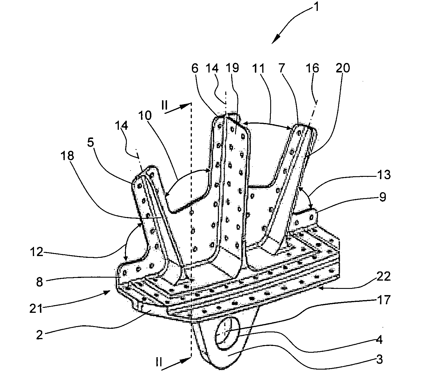
[0021]FIG. 1 shows a fitting according to an embodiment the invention in a perspective view.

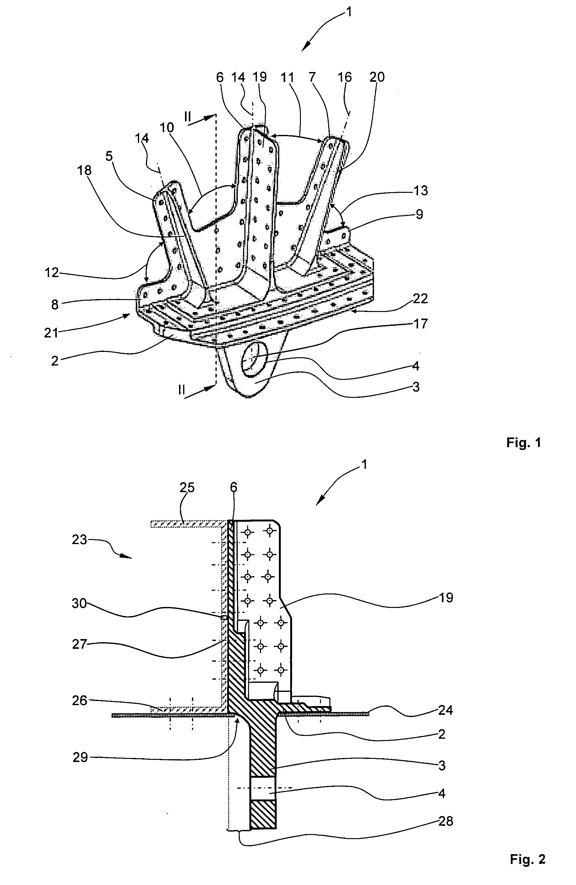
[0022]The one-piece fitting 1 comprises a shoulder plate 2, on the underside of which a lug shackle 3 with a lug 4 is arranged. The lug shackle 3 with the lug 4 serves for connecting further components, which are not represented, in particular components of an undercarriage for an aircraft. Arranged above the shoulder plate 2 are fastening shackles 5 to 7, which form with the shoulder plate 2 an included angle of approximately 90°. The fastening shackles 5 and 7 are laterally adjoined by two smaller flanges 8, 9. The flanges 8, 9 run along the rear edge of the shoulder plate 2 and stand upright on the shoulder plate 2. The fastening shackles 5 to 7 and the flanges 8, 9 have a pattern of holes with a multiplicity of holes, which are not designated but through which the fastening of the fitting 1 to a frame of a fuselage cell that is not represented in FIG. 1 takes place by means of rivets and / ...


PUM


Abstract

Disclosed is a fitting for introducing great loads into a fuselage cell of an aircraft, in particular those which emanate from undercarriage components or are introduced into them. The fitting has a shoulder plate for bearing against the inside of the skin of the fuselage cell for example over its full surface area. Arranged underneath the shoulder plate is a vertical lug shackle with a lug for introducing the loads, wherein the lug shackle is led to the outside through a clearance in the skin of the fuselage cell. At least one approximately upright fastening shackle is provided on the upper side of the shoulder plate for connecting the fitting to a frame web. According to the invention, the loads occurring are introduced into the frame, substantially “moment-free” in the region of a neutral fiber, so that the said frame is not exposed to any appreciable flexural stresses and can be of a more lightweight design. The frame becomes the load introducing instrument and distributes the loads uniformly into the skin of the fuselage cell. Radially acting loads are transferred from the shoulder plate directly into the skin of the fuselage cell by way of shearing.

Description

CROSS-REFERENCE TO RELATED APPLICATIONS[0001]This application claims the benefit of U.S. Provisional Application No. 60 / 881,640, filed Jan. 22, 2007 and German patent application No. 10 2007 011 613.8, filed Mar. 9, 2007, the entire disclosures of which are herein incorporated by reference.FIELD OF THE INVENTION[0002]The invention relates to a fitting, in particular a landing gear fastening fitting or undercarriage fastening fitting, for introducing high forces into a fuselage cell of an aircraft stiffened with a multiplicity of frames and having a lug shackle, in which a lug for introducing the forces, in particular the forces emanating from undercarriage components, is arranged.BACKGROUND OF THE INVENTION[0003]The introduction of high external loads into the fuselage structure of an aircraft involves complex structural design requirements and intensive weight requirements. Until now, two variants have been used for the connection in aircraft construction. Such forms of load occur,...

Claims


Application Information

Patent Timeline
IPC IPC(8): B64C1/06
CPCB60P7/0807B64D9/00Y02T50/46B64D9/003Y02T50/40
Inventor BENTHIEN, HERRMANN
Owner AIRBUS OPERATIONS GMBH
Learn More