

Patterning method
a patterning and patterning technology, applied in the field of patterning methods, can solve problems such as not being able to achieve optimal designs for case models, and achieve the effect of increasing the additional value of technical products besides functional performances
- Summary
- Abstract
- Description
- Claims
- Application Information
AI Technical Summary
Benefits of technology
Problems solved by technology
Method used
Image

Examples
first embodiment
The First Embodiment
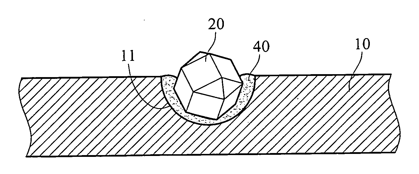
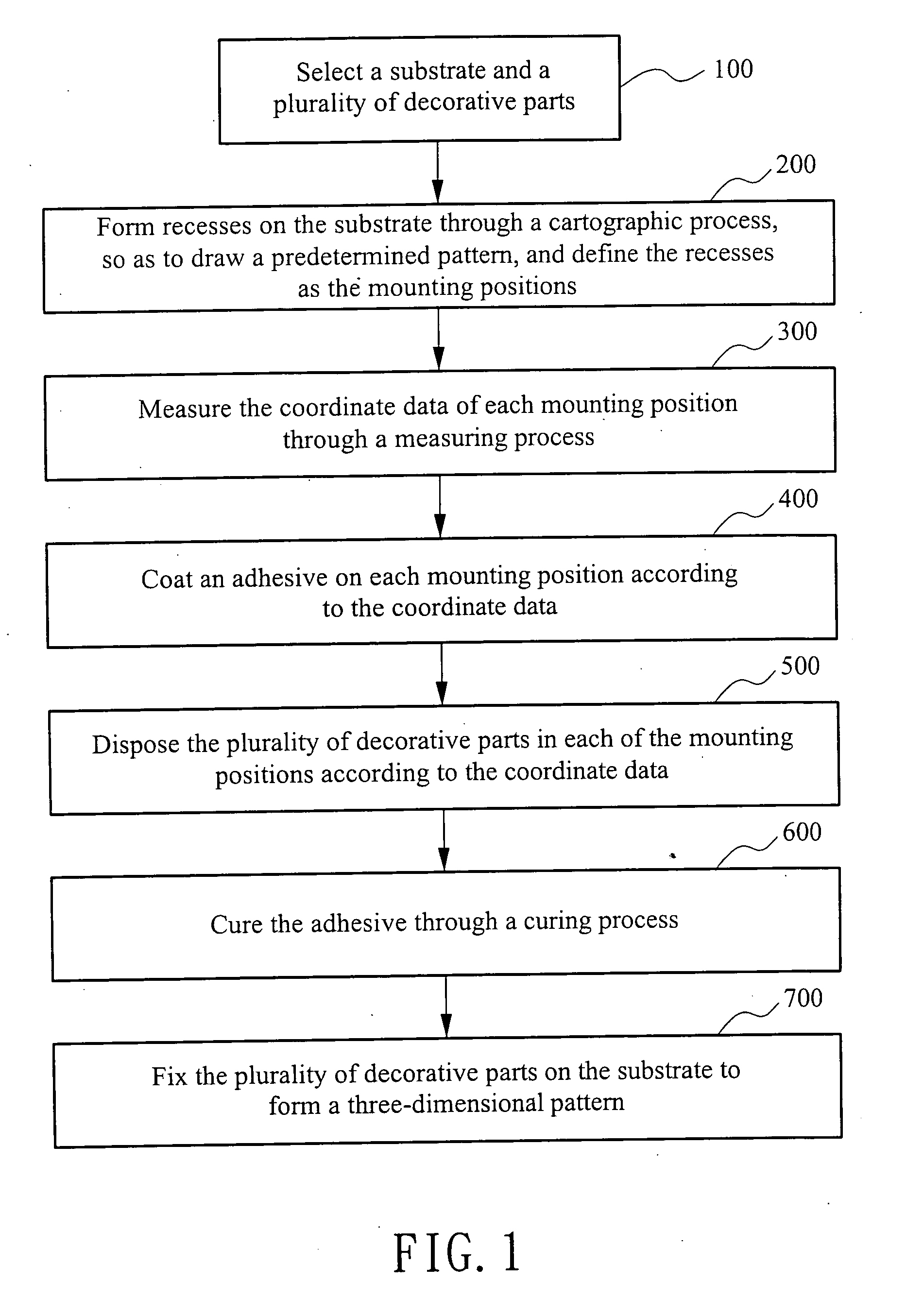
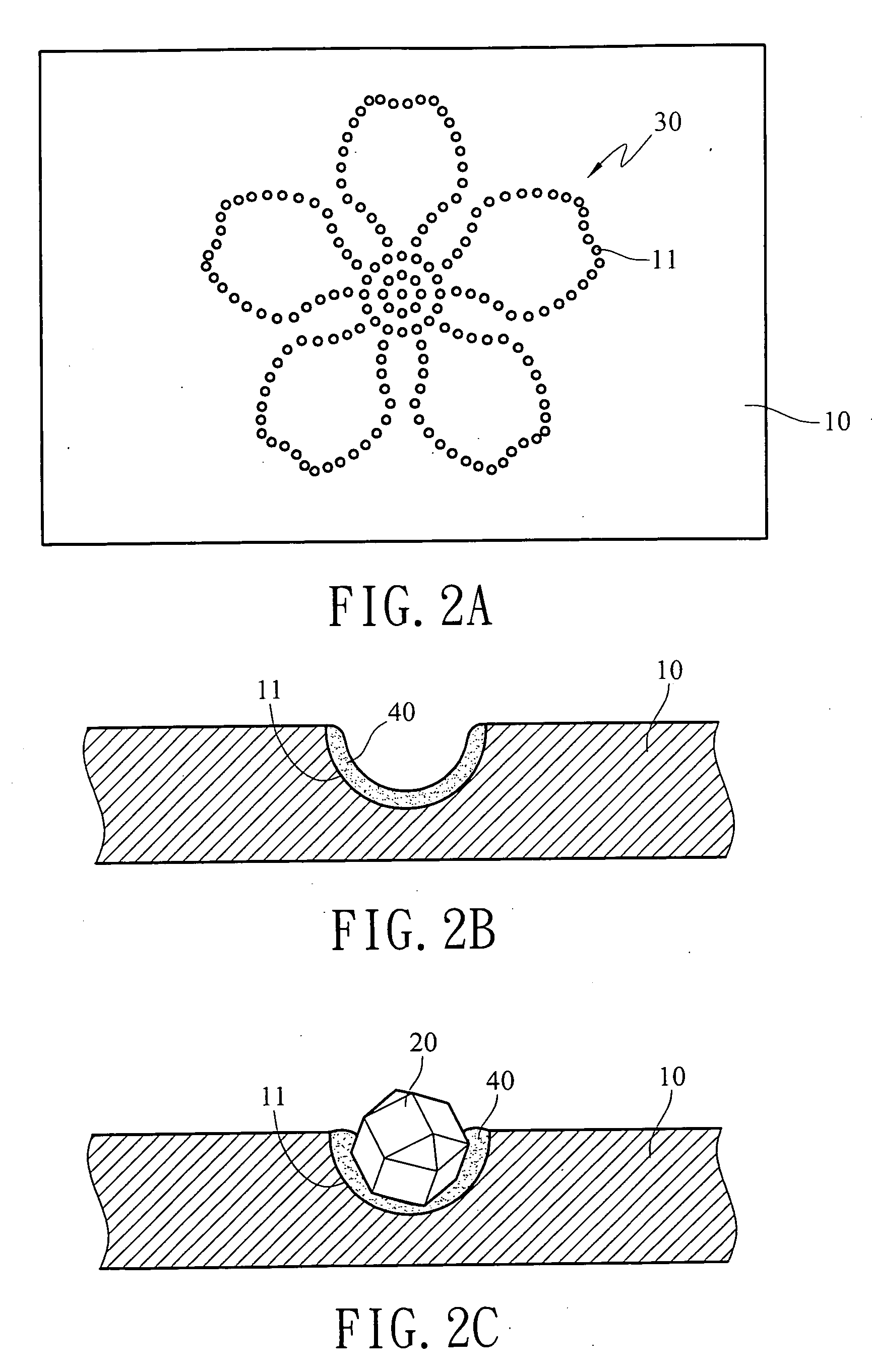
[0023]As shown in FIG. 1, in the patterning method according to a first embodiment of the present invention, a substrate 10 and a plurality of decorative parts 20 is selected first (Step 100), wherein the substrate 10 is made of an Mg—Al alloy material, and the plurality of decorative parts 20 is diamonds. A plurality of recess 11 is formed on a surface of the substrate 10 through a cartographic process of laser engraving, so as to draw a predetermined pattern 30 (Step 200, referring to FIG. 2A), the predetermined pattern may be a graphic, a symbol or a character, for example, a flower pattern, as shown in FIG. 2A, and each recess 11 is used to dispose one decorative part 20 and is defined as a mounting position. The coordinate data of each mounting position is measured through a measuring process (Step 300), wherein the measuring process is calculating by using a coordinate measuring machine (CMM). Through the bonding process of adhesive, an adhesive 40 is coate...
second embodiment
The Second Embodiment
[0026]As shown in FIG. 4, the patterning method according to a second embodiment of the present invention includes the following steps. First, a substrate 10 and a plurality of decorative parts 20 is selected (Step 100), wherein the substrate 10 is made of an Mg-Al alloy material, and the plurality of decorative parts 20 is diamonds. A plurality of recesses 11 is formed on an upper surface of the substrate 10 through a cartographic process of CNC, so as to draw a predetermined pattern 30 (Step 200), wherein the cartographic process of CNC includes steps of drawing a digital graphic file via a computer in advance, and inputting the digital graphic file to the CNC, such that the CNC fabricates the recesses 11 on the substrate 10 through a work piece such as a milling cutter according to the data document of digital graphic file, and each of the recesses 11 is used to dispose a decorative part 20 and is defined as a mounting position. Through a bonding process of a...
third embodiment
The Third Embodiment
[0029]As shown in FIGS. 5A, 5B, in the patterning method according to a third embodiment of the present invention, the processing steps are the same as those of the first embodiment or the second embodiment, that is, the cartographic processes such as laser engraving, semi-automatic mechanical drilling and milling, CNC, stamping device, or plastic injection molding machine are employed. As for the cartographic process used in the third embodiment of the present invention, a predetermined pattern 30 is drawn through forming through holes 12 on the substrate 10, an adhesive surface 121 is formed on the inner wall of the through hole 12, and depending upon the characteristics of different materials of the substrate 10 and the decorative parts 20, different bonding processes are employed. For example, the bonding process of adhesive is coating the adhesive 40 on the adhesive surface 121, as described in the first and second embodiments. Or, the through hole 12 is fab...
PUM
| Property | Measurement | Unit |
|---|---|---|
| Temperature | aaaaa | aaaaa |
Abstract
Description
Claims
Application Information