
Apparatus, system, and method for timing based servo tape formating

a timing-based servo tape and formatting technology, applied in the field of tape formatting, can solve the problems that the longitudinal velocity of the tape cannot be calculated, and the resultant spacing of the “b” transition cannot be compensated in the magnetic tape drive, so as to reduce the read and write errors, increase the read and write speed

Inactive Publication Date: 2008-07-24
IBM CORP
View PDF8 Cites 117 Cited by
  • Summary
  • Abstract
  • Description
  • Claims
  • Application Information

AI Technical Summary

Benefits of technology

[0010]From the foregoing discussion, there is a need for an apparatus, system, and method that precisely formats magnetic tape with timing-based servo patterns. Beneficially, such an apparatus, system, and method would reduce read and write errors for data stored on the magnetic tape and support increased read and write speeds.
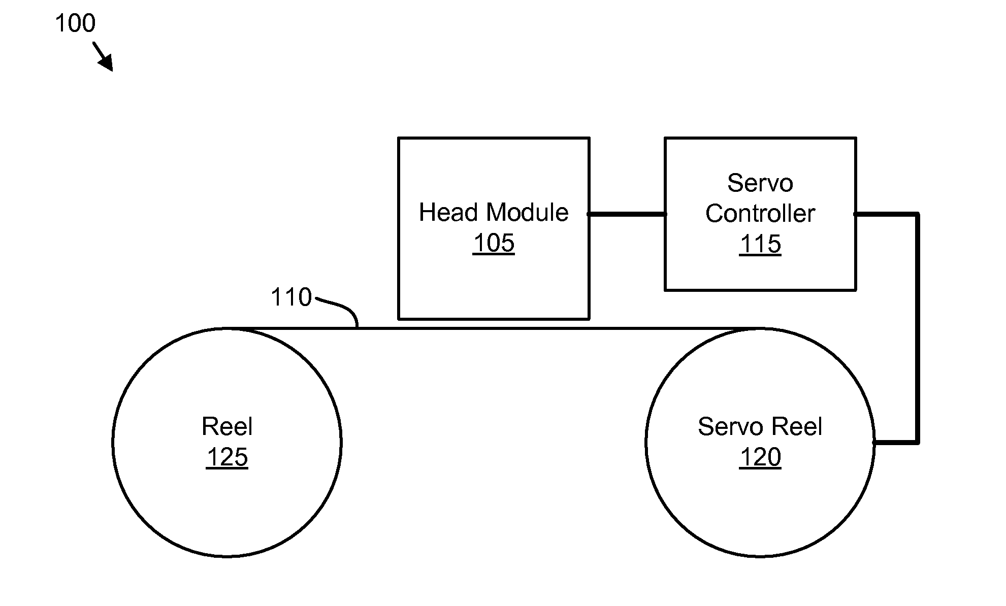
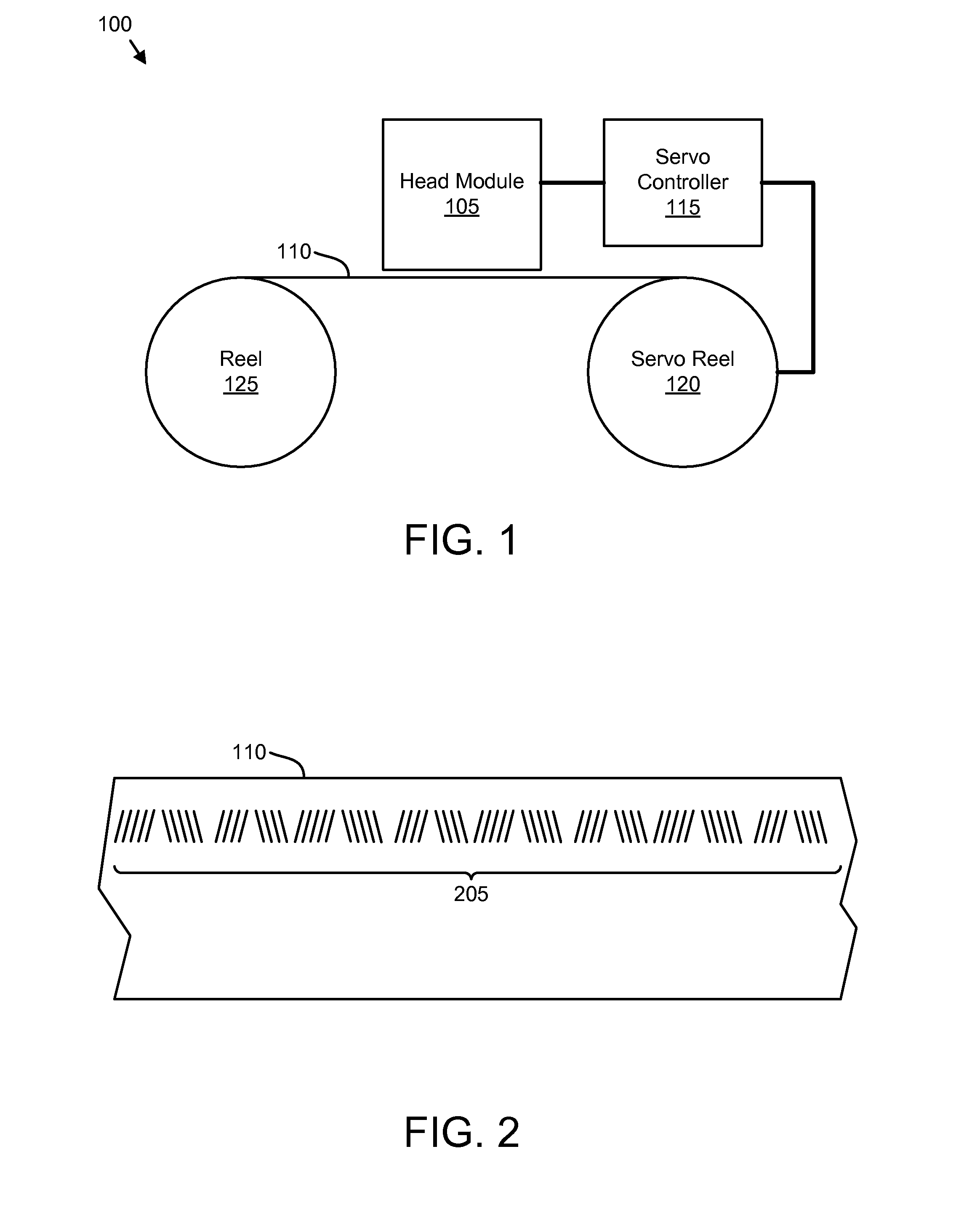
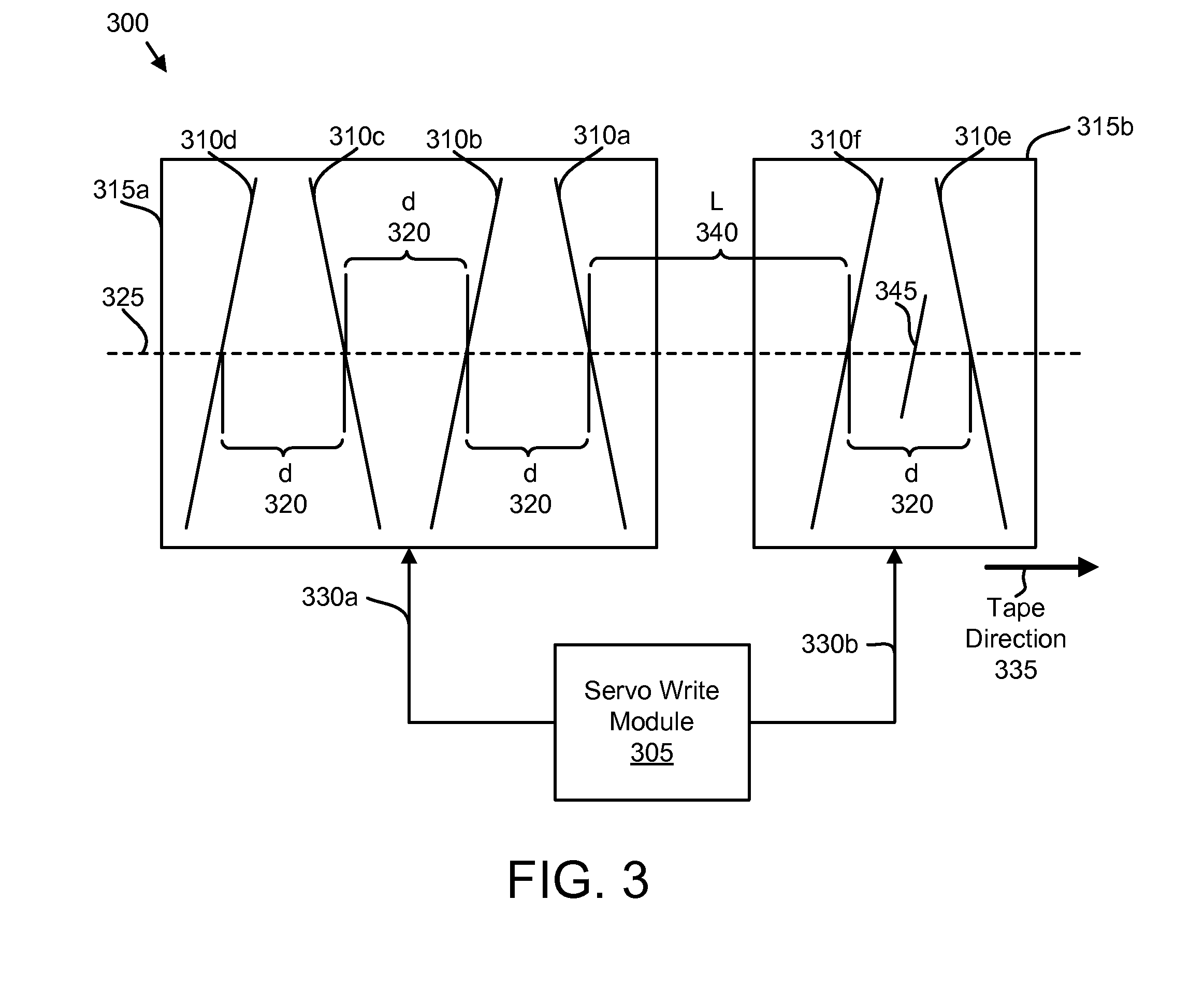
[0019]The second write head may include a read element configured to detect a stripe written by the first write head. The fifth and sixth write elements may write the incremental number of stripes in response to detecting the written stripe. In another embodiment, the first write head comprises a read element configured to detect a stripe written by the second write head. The first write head may write the base number of stripes to response to detecting the written stripe. The system allows the precise placement of stripe patterns for timing-based servo patterns.
[0026]The embodiment of the present invention formats timing-based servo patterns by writing stripe patterns with a plurality of write elements. In addition, the present invention may improve the precision with precisely placed write elements. These features and advantages of the present invention will become more fully apparent from the following description and appended claims, or may be learned by the practice of the invention as set forth hereinafter.

Problems solved by technology

Thus substantial error in the velocity of the tape by the servo writer drive or substantial error in the timing between the pulses, results in an error in the “b” distance and hence an error in the lateral position calculated based on the “b” pulse timing.
Thus substantial error in the velocity of the tape by the servo writer drive or substantial error in the timing between the pulses, results in an error in the “b” distance and hence an error in the longitudinal velocity of the tape calculated based on the “b” pulse timing.
Error in the resultant spacing of the “b” transitions cannot be compensated for in the magnetic tape drive because the error is written into the magnetic tape in the servo pattern.

Method used


Image

  • Apparatus, system, and method for timing based servo tape formating
  • Apparatus, system, and method for timing based servo tape formating
  • Apparatus, system, and method for timing based servo tape formating

Examples


Embodiment Construction

[0036]Some of the functional units described in this specification have been labeled as modules, in order to more particularly emphasize on their implementation independence. For example, a module may be implemented as a hardware circuit comprising custom VLSI circuits or gate arrays, off-the-shelf semiconductors such as logic chips, transistors, or other discrete components. A module may also be implemented in programmable hardware devices such as field programmable gate arrays, programmable array logic, programmable logic devices or the like.

[0037]References throughout this specification to “one embodiment,”“an embodiment,” or similar language means that a particular feature, structure, or characteristic described in connection with the embodiment is included in at least one embodiment of the present invention. Thus, appearances of the phrases “in one embodiment,”“in an embodiment,” and similar language throughout this specification may, but do not necessarily, all refer to the sa...


PUM


Abstract

An apparatus, system, and method are disclosed for formatting a timing-based servo pattern on a magnetic tape. A first write head concurrently writes a base number of stripes to a plurality of first stripe patterns with a first and third element and writes the base number of stripes to a plurality of second stripe patterns with a second and fourth element of a first write head in response to at least one first write signal. A second write head concurrently writes an incremental number of stripes to a specified first stripe pattern to form a first incremental stripe pattern with a fifth write element and writes the incremental number of stripes to a specified second stripe pattern to form a second incremental stripe pattern with a sixth write element.

Description

BACKGROUND OF THE INVENTION[0001]1. Field of the Invention[0002]This invention relates to tape formatting and more particularly relates to timing-based servo tape formatting.[0003]2. Description of the Related Art[0004]Magnetic tape provides a means for physically storing data to longitudinal tracks of a magnetic tape moved longitudinally with respect to read and / or write heads. One method for maximizing the amount of data that can be stored is to maximize the number of parallel tracks on the media, and that is typically accomplished by employing servo systems which provide track following and allow the tracks to be spaced very closely. Another method for maximizing the amount of data that can be stored is to maximize the amount of data that can be stored on an individual track, and often the recording and detection arrangements require that the longitudinal movement of the magnetic tape be kept relatively constant in order to maximize the data density of a track. Still another meth...

Claims


Application Information

Patent Timeline
IPC IPC(8): G11B5/09
CPCG11B5/584
Inventor BATES, ALLEN KEITHBUI, NHAN XUANHUTCHINS, ROBERT ALLENTAYLOR, MARK ALLAN
Owner IBM CORP
Learn More