Controlling the position of an agricultural implement coupled to an agricultural vehicle based upon three-dimensional topography data

a technology of topography data and control system, applied in the field of system for controlling the position of agricultural implement coupled to an agricultural vehicle, can solve the problems of severe and expensive damage to the header, inability to cause a sufficiently fast lifting of the header, and the accumulation of debris such as rocks, so as to achieve high speed without a risk of ground incidents

Active Publication Date: 2008-07-24
DEERE & CO
View PDF21 Cites 68 Cited by
  • Summary
  • Abstract
  • Description
  • Claims
  • Application Information

AI Technical Summary

Benefits of technology

[0015]It is an advantage of the present invention that the position control signals for the implement are provided in a simple and reliable manner, since a location signal generation arrangement like a Global Positioning System (GPS) reception antenna is provided on many agricultural vehicles, and the three-dimensional topographic database does not involve significant additional expense. The operator can operate the implement close to the ground at a relatively high speed without a risk of ground incidents even when a rapid slope change is encountered.
[0016]The expected or predictive required position change data can be recalled from the field topography database based upon heading data that contains information about the forward direction (seen in a horizontal plane, e.g. an angle measured with respect to the south-north direction) and preferably about the speed of the vehicle. This heading data can be obtained by subtracting two subsequent positions from the location signal generation arrangement and/or using data differences from two spaced location signal generation arrangements mounted to the vehicle and/or using a signal from a compass and/or using a signal from an inertial navigation system and/or by using a signal from a steering system of the vehicle.
[0017]The control unit can a

Problems solved by technology

One disadvantage of these sensors mounted to the header and interacting with the ground below the header, even if they are mounted at the forward end of the header, as on a divider tip (see, for example, U.S. Pat. No. 6,813,873), is that they are not able to cause a sufficiently fast lifting of the header when the header is approaching sharp rises in the ground topography.
Due to the position of the sensor and the reaction time of the actuator, collisions with the ground cannot always be avoided, causing severe and expensive damage to the header.
Additionally, debris such as rocks can be collected and damage parts of the header and of the harvesting machine.
This problem is greater with the relatively high ground speeds of actual harvesting machines, si

Method used


Image

  • Controlling the position of an agricultural implement coupled to an agricultural vehicle based upon three-dimensional topography data
  • Controlling the position of an agricultural implement coupled to an agricultural vehicle based upon three-dimensional topography data
  • Controlling the position of an agricultural implement coupled to an agricultural vehicle based upon three-dimensional topography data

Examples


Embodiment Construction

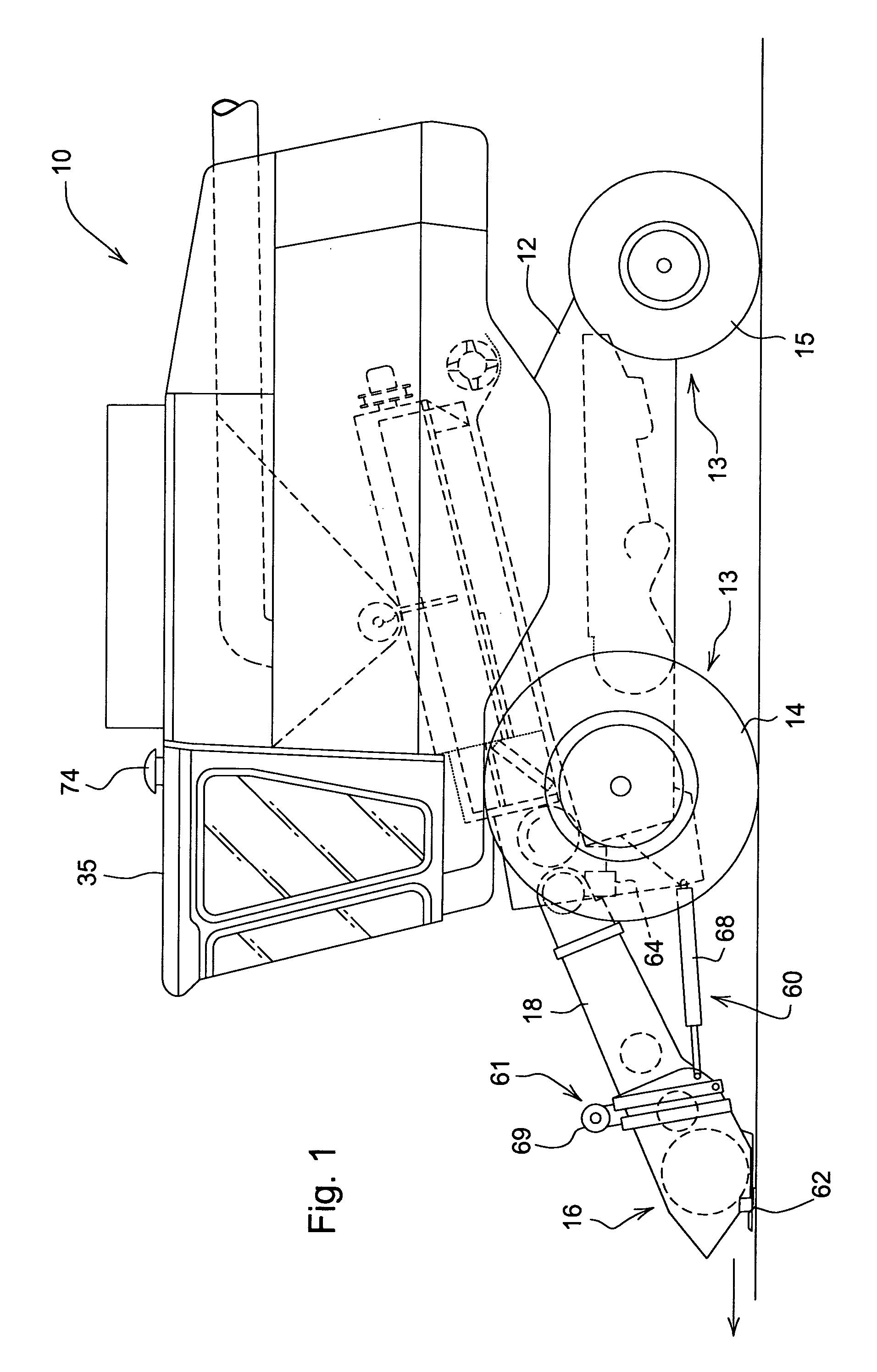
[0026]Referring now to FIG. 1, therein is shown an agricultural vehicle in the form of a harvester or combine 10 comprising a main frame 12 having wheel structure 13 including front and rear ground engaging wheels 14 and 15 supporting the main frame 12 for forward movement over a field of crop to be harvested. Although wheels 14 and 15 are shown, the wheel structure 13 could include or be composed of ground engaging tracks. In the following, references to directions (like forward) are cited with respect to the forward direction of combine 10 that is directed to the left in FIG. 1 as shown by the arrow.

[0027]An implement in the form of a header or harvesting platform 16 is used for harvesting a crop and directing it to a feederhouse 18. The feederhouse 18 is pivotally connected to the frame 12 around a horizontal axis extending transversely to the forward direction such that the platform 16 is vertically adjustable. The feederhouse 18 includes a conveyor (not shown) for conveying the...


PUM


Abstract

A system for controlling the position of an agricultural implement coupled to an agricultural vehicle comprises a control unit connected to a field topography database containing three-dimensional data of the topography of a field, a location signal generation arrangement providing location data of the position of the vehicle and/or the implement in the field, an implement position sensor arranged to sense the position of the implement with respect to the ground and to a positioning arrangement configured to move the implement in response to position control signals from the control unit. The control unit is operable to provide the control signals based upon a combination of actual position data received from the implement position sensor and expected required position change data that are derived from elevation data recalled from the field topography database based upon the location data.

Description

FIELD OF THE INVENTION [0001]The present invention relates to a system for controlling the position of an agricultural implement coupled to an agricultural vehicle.BACKGROUND OF THE INVENTION [0002]A number of agricultural implements need to be moved during work in a position relatively close to the ground of a field. However, in order to avoid damage, a contact between the implement and the ground needs to be avoided.[0003]A typical example is a header for a self-propelled harvesting machine like a combine harvester or a forage harvester. Such headers include grain cutting platforms, corn pickers and corn cutting machines. In the prior art, mechanical ground height sensors have been used for an automatic header height control. These ground height sensors are pivotally mounted below the frame of the header such that they pivot around an axis extending horizontally and transversely to the forward direction and have a surface in mechanical contact with the ground. A potentiometer is c...

Claims


Application Information

Patent Timeline
IPC IPC(8): G06F19/00
CPCA01D41/141A01B69/004
Inventor PICKETT, TERENCE DANIELHAN, SHUFENG
Owner DEERE & CO
Why Eureka
Try Eureka