Satellite Signal Frequency Translation and Stacking

a satellite signal and frequency translation technology, applied in satellite broadcast receiving, broadcast receiving circuits, television systems, etc., can solve the problems of interruption and temporary loss of service at the affected port, degrading signal quality as well, and increasing complexity, so as to reduce complexity, reduce cost, and avoid discontinuity in impedance.

Active Publication Date: 2008-07-24
ENTROPIC COMM INC
View PDF19 Cites 20 Cited by
  • Summary
  • Abstract
  • Description
  • Claims
  • Application Information

AI Technical Summary

Benefits of technology

[0017]Several satellite signals are received and amplified. A switch matrix selects two or more signals from among the received RF signals. Switching is preferably performed with switches that maintain constant impedance on the input terminal or provide a slow switching transition to avoid a discontinuity in impedance. The selected signals are down converted and frequency translated to a high or low band-stacked band. The translated signals are combined in pairs to form a band-stacked signal. A single downconversion step is used, thereby reducing complexity, cost, and phase noise. The band-stacked signal feeds tuners in STBs.
[0018]The present invention reduces the complexity, cost and size of channel-band frequency translation and stacking by eliminating secondary frequency conversion in the outdoor unit (ODU) and corresponding circuitry. Elimination of the second frequency conversion also helps preserve the quality of the signals.

Problems solved by technology

It is a challenge to provide the capability of reception of any channel from any path on multiple tuners in different receive appliances simultaneously and independently.
These and other prior art systems, while accomplishing the goal of independent tuning of multiplicity of tuners, achieve that by employing a secondary frequency conversion, effectively adding one more conversion to the conversion already occurring in the LNB, thus not only increasing the complexity, but potentially degrading the signal quality as well.
Furthermore, if the switch-over in the matrix switch creates a transient and results in a change of level and phase of the received signal, interruption and temporary loss of service can occur at the affected port.

Method used


Image

  • Satellite Signal Frequency Translation and Stacking
  • Satellite Signal Frequency Translation and Stacking
  • Satellite Signal Frequency Translation and Stacking

Examples


Embodiment Construction

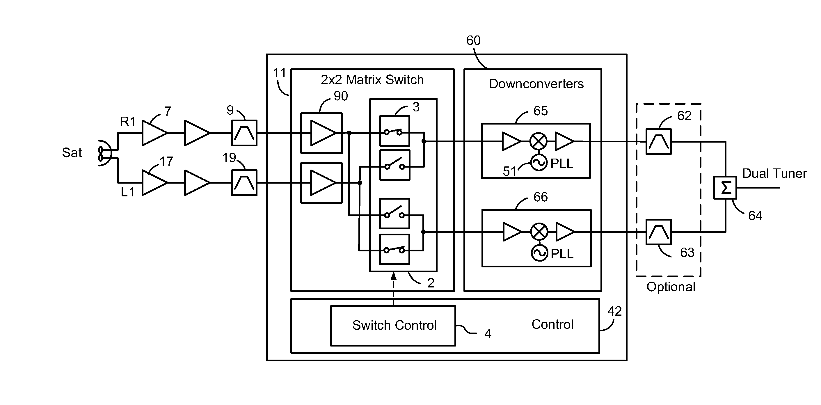
[0047]FIG. 4 shows a block diagram of one embodiment of the present invention of a satellite channel translation system for one satellite, providing one output containing two channels at different frequencies and feeding a dual channel tuner or two individual tuners. Each tuner is provided with the desired signal from either received polarity, but unlike the prior art circuits, achieves the translation directly without performing a secondary frequency conversion.

[0048]The entire switching and routing function is performed at the input frequency (“on-frequency”) thus eliminating oscillators, mixers, bypass switches, post-amplifiers, and other circuitry associated with the secondary conversion. This approach simplifies the system as well as improves preservation of the signal integrity. Where it is necessary to minimize the effects of port-to-port cross-talk during the switch-over, the switch control circuit 4 may be used to control the switching timing and the impedance transition of...


PUM


Abstract

An outdoor satellite receiving unit (ODU) receives several independent satellite signals, selects two signals with a switch matrix, downconverts the two signals to a bandstacked signal with a high and a low band signal, and outputs the bandstacked signal on the same cable to receiver units. Several satellite signals can be selected in groups of two or more and output to independent receiver units. Signal selecting is performed at the received radio frequency (RF) and bandstacking is performed with a single downconversion step to an intermediate frequency (IF). Channel stacking on the same cable of more than two channels from several satellites can be achieved by using frequency agile downconverters and bandpass filters prior to combining at the IF output. A slow transitioning switch minimizes signal disturbances when switching and maintains input impedance at a constant value.

Description

RELATED APPLICATIONS[0001]This application is a continuation application of U.S. non-provisional application No. 11 / 934,715, filed Nov. 2, 2007, entitled “Satellite signal frequency translation and stacking,” incorporated herein by reference, said 11 / 934,715 non-provisional application claiming the benefit of U.S. provisional application No. 60 / 864,352 filed Nov. 3, 2006, entitled “Satellite signal frequency translation and stacking”, incorporated herein by reference, U.S. provisional application No. 60 / 885,814 filed Jan. 19, 2007 entitled “Circuits, Systems and Methods for Constructing a Composite Signal”, incorporated herein by reference, and U.S. provisional application No. 60 / 886,933 filed Jan. 28, 2007 entitled “Circuits, Systems and Method for Frequency Translation and Signal Distribution”, incorporated herein by reference.BACKGROUND OF THE INVENTION[0002]1. Field of the Invention[0003]The present invention relates generally to satellite receiver systems, and in particular, to...

Claims


Application Information

Patent Timeline
Patent Type & Authority Applications(United States)
IPC IPC(8): H04N7/20
CPCH04H40/90H04B1/28H04B1/16
Inventor PETROVIC, BRANISLAVHANCOCK, DALEGOLDBLATT, JEREMYBARGROFF, KEITH
Owner ENTROPIC COMM INC
Why Eureka
Try Eureka