Single Cycle Apparatus for Condensing Water from Ambient Air

Inactive Publication Date: 2008-07-31
JONES DARRYL JOHN +1
View PDF3 Cites 16 Cited by
  • Summary
  • Abstract
  • Description
  • Claims
  • Application Information

AI Technical Summary

Benefits of technology

[0010]contacting the cooled condensation surface with the ambient air to eff

Problems solved by technology

However, the step of heating the solution

Method used


Image

  • Single Cycle Apparatus for Condensing Water from Ambient Air
  • Single Cycle Apparatus for Condensing Water from Ambient Air
  • Single Cycle Apparatus for Condensing Water from Ambient Air

Examples


embodiment 190

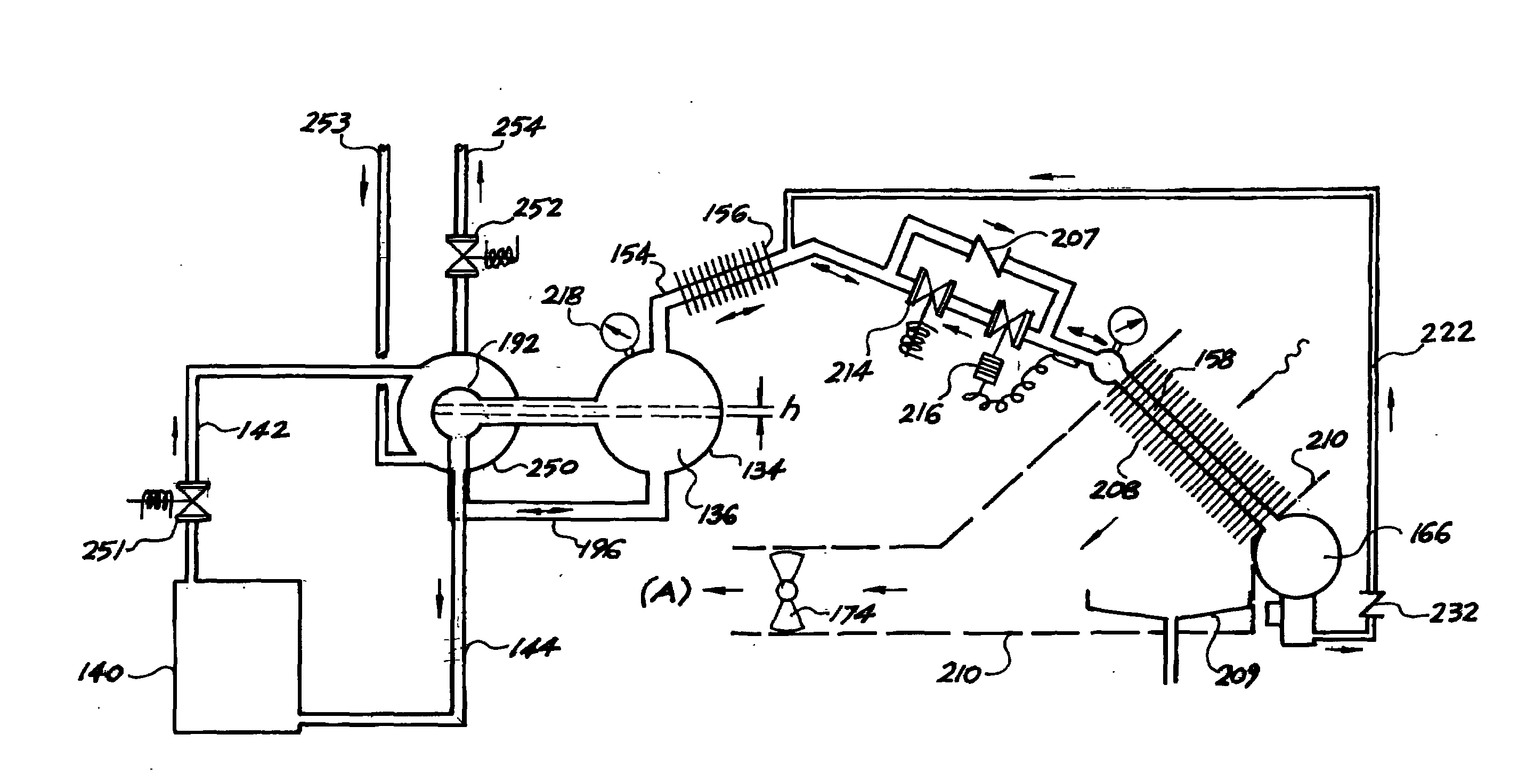
[0117]A further embodiment 190 of the present invention is illustrated in FIG. 11. This embodiment differs from that shown in FIG. 10 in that the fan 174 blows ambient air across the cooling fins 170 of the evaporator 166 during the first stage of the work cycle which is then directed to rectifier cooling fins 191. The ambient air draws off heat from the rectifier fins causing the gaseous ammonia in the conduit trap 158 to condense. The ambient air also draws off heat from gaseous ammonia flowing into the evaporator which has not condensed in the conduit trap 158, causing the remaining gaseous ammonia to condense and collect in the evaporator. The evaporator 166 in this embodiment therefore serves as both a condenser for condensation of the gaseous ammonia and to facilitate evaporation of gaseous ammonia from the liquid ammonia for return to the heating tank during the second stage of the work cycle.

[0118]During the second stage of the work cycle, the fan continues to operate such t...

embodiment 200

[0121]A yet further embodiment 200 of the present invention is shown in FIG. 12. In this apparatus, a solenoid operated control valve 202 is provided which is opened during the first stage of the work cycle of the apparatus to allow the flow of ammonia to the evaporator 166. The control valve 202 is closed for the second stage of the work cycle, and the flow rate of gaseous ammonia returning to the heating tank 134 is controlled by throttle valve 204 arranged in the conduit trap 158. The throttle valve incorporates a fluid expansion thermostat 206 for sensing the temperature of the cooling fins 170 of the evaporator 166 and effecting opening or closing of the throttle valve in response to variation in the temperature, to regulate evaporation of the liquid ammonia and thereby condensation of water from the ambient air.

[0122]For any given prevailing atmospheric conditions, there is a specific humidity value measured in grams of water vapour per kilogram of air. For example, a specific...


PUM

PropertyMeasurementUnit
Percent by massaaaaaaaaaa

Abstract

In one aspect of the present invention there is provided a method for condensing water from ambient air, the method comprising: providing at least one condensation surface for contact with the ambient air; heating a solution of a refrigerant and a fluid, to drive gaseous refrigerant from the solution; cooling the gaseous refrigerant to condense the gaseous refrigerant into liquid refrigerant, and collecting the liquid refrigerant; evaporating refrigerant from the liquid refrigerant such that heat is exchanged between the refrigerant and the condensation surface which is thereby cooled to, or below, the dew point of the water in the ambient air; and contacting the cooled condensation surface with the ambient air to effect condensation of water from the ambient air onto the condensation surface. In another aspect of the present invention there is provided an apparatus for condensing water from ambient air, the apparatus comprising: heating means for heating a solution of a refrigerant and a fluid, to drive evaporation of the refrigerant from the solution to produce gaseous refrigerant; cooling means for cooling the gaseous refrigerant such that the gaseous refrigerant condenses into liquid refrigerant; and an evaporator having at least one condensation surface for contact with the ambient air and being arranged for collecting the liquid refrigerant, and subsequent evaporation of gaseous refrigerant from the liquid refrigerant; wherein the condensation surface is arranged for being cooled to, or below, the dew point of the water in the ambient air by heat exchange between the refrigerant and the condensation surface upon evaporation of the refrigerant from the liquid refrigerant, and thereby effecting condensation of water from the ambient air onto the condensation surface.

Description

FIELD OF THE INVENTION[0001]The present invention broadly relates to a method and apparatus for condensing water from ambient air and collecting the water for use. The apparatus in at least one form provides a means for generating portable water for consumption or other purposes and finds particular application in areas where portable water supplies are limited. The invention also relates to a method and apparatus' for providing heating and / or cooling during a work cycle of the apparatus.BACKGROUND OF THE INVENTION[0002]In many locations around the world access to a fresh portable water supply is limited, forcing many to use water for everyday needs that would not generally be deemed suitable for such use. Indeed, many water supplies are contaminated or polluted and in order to be able to use the water safely, it is necessary for the water to be boiled or treated in some other way.[0003]While yachts and ships carry their own water supplies during a voyage, it is often necessary to r...

Claims


Application Information

Patent Timeline
IPC IPC(8): F24F3/14F25B27/00
CPCB01D5/0039E03B3/28F24F13/22F25B15/10F25B17/02F25B27/007F25B37/00F25B49/04F28F17/005Y02A20/00
Inventor JONES, DARRYL JOHNCOLLINS, GRAEME ALLAN
Owner JONES DARRYL JOHN
Why Eureka
Try Eureka