
Vehicular wind power generation device

a technology of wind power generation and electric motor, which is applied in the direction of electric generator control, machines/engines, propulsion parts, etc., can solve the problems of increasing prices, increasing air pollution, and scarce crude oil ever being scarcer, so as to tackle air pollution and other forms of pollution

Inactive Publication Date: 2008-07-31
YEH YANG CHING +3
View PDF10 Cites 27 Cited by
  • Summary
  • Abstract
  • Description
  • Claims
  • Application Information

AI Technical Summary

Benefits of technology

[0011]In view of the existing drawbacks of the prior art, the present invention provides a vehicular wind power generation device with a view to overcome the existing drawbacks of electrically driven vehicles, such as limited power storage capacity, frequent charging, and lack of ease of use, and to solve the pollution caused by hydrocarbon vehicles. To achieve the aforesaid objectives, the present invention provides a vehicular wind power generation device for supplying rechargeable power to a vehicle. The vehicle comprises a bumper facing and guiding a windward current. The vehicular wind power generation device of the present invention comprises a wind guiding hood with at least a wind guiding inlet and at least a wind guiding outlet communicating therewith, a directing-rotating element disposed at the wind guiding outlet, a power generator, and a power storage unit. The windward area of the wind guiding inlet is greater than that of the wind guiding outlet. The wind guiding inlet is connected to the bumper so as to receive a windward current guided by the bumper. The windward current is blown out of the wind guiding outlet and received by the directing-rotating element. The power generator is connected to the directing-rotating element and the power storage unit for storing power while the power generator is operating. The directing-rotating element is rotated by the windward current blowing toward the directing-rotating element while the vehicle is in motion, thus enabling the power generator to operate and generate power, and eventually the power generated is stored in the power storage unit.
[0013]With a vehicular wind power generation device of the present invention, a power generator driven by a directing-rotating element operates and generates power continuously while a vehicle is in motion, thus providing rechargeable power for the vehicle continuously. The known inconvenience caused by insufficient power storage and therefore frequent charging is eliminated by the present invention, not to mention that the present invention is efficient in tackling air pollution and other forms of pollution.

Problems solved by technology

However, resources of crude oil have never been scarcer than they are now, and their prices are increasingly high.
The greenhouse effect, which arises from decades of consumption of petroleum, and other types of pollution are becoming more serious.
Generally speaking, power storage capacity of vehicular cells, however, is quite limited if not little, compared to the petroleum fuel for driving an internal combustion-based means of transportation.
As a result, electric vehicles have their drawbacks, such as inevitably short drives, frequent charging, slow charging, time-consuming charging, lack of ease of use, and lack of user-friendliness.
Accordingly, electric vehicles are not in wide use.
Solar vehicles are not in wide use because of unreliable sources of sunlight and bulky solar panels.
Vehicles powered by fuel cells are also not in wide use, because fuel cells are bulky and expensive.
Accordingly, what is in urgent need of a solution is that, the electric vehicles put on the market by the industrial sector are faced with plenty unsolved user-unfriendly problems.

Method used


Image

  • Vehicular wind power generation device
  • Vehicular wind power generation device
  • Vehicular wind power generation device

Examples


Embodiment Construction

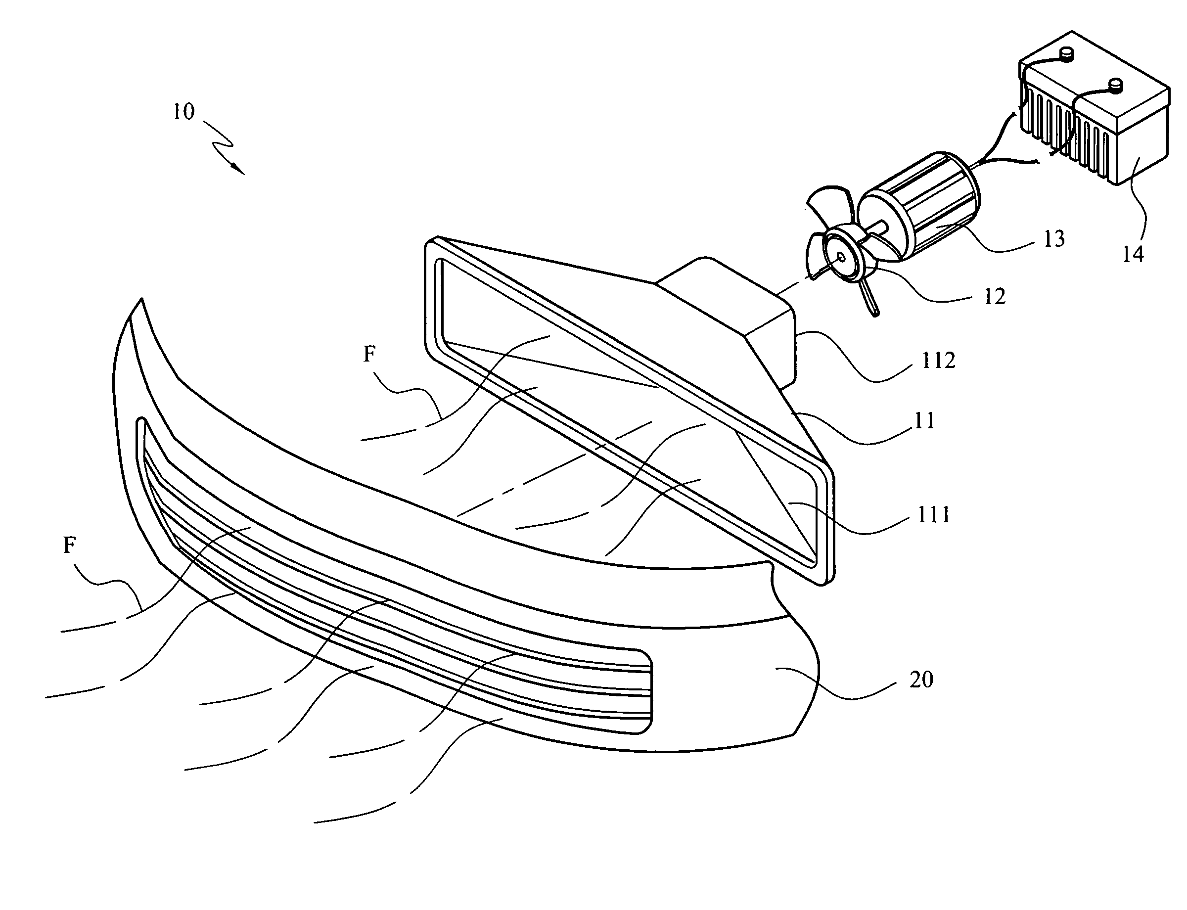
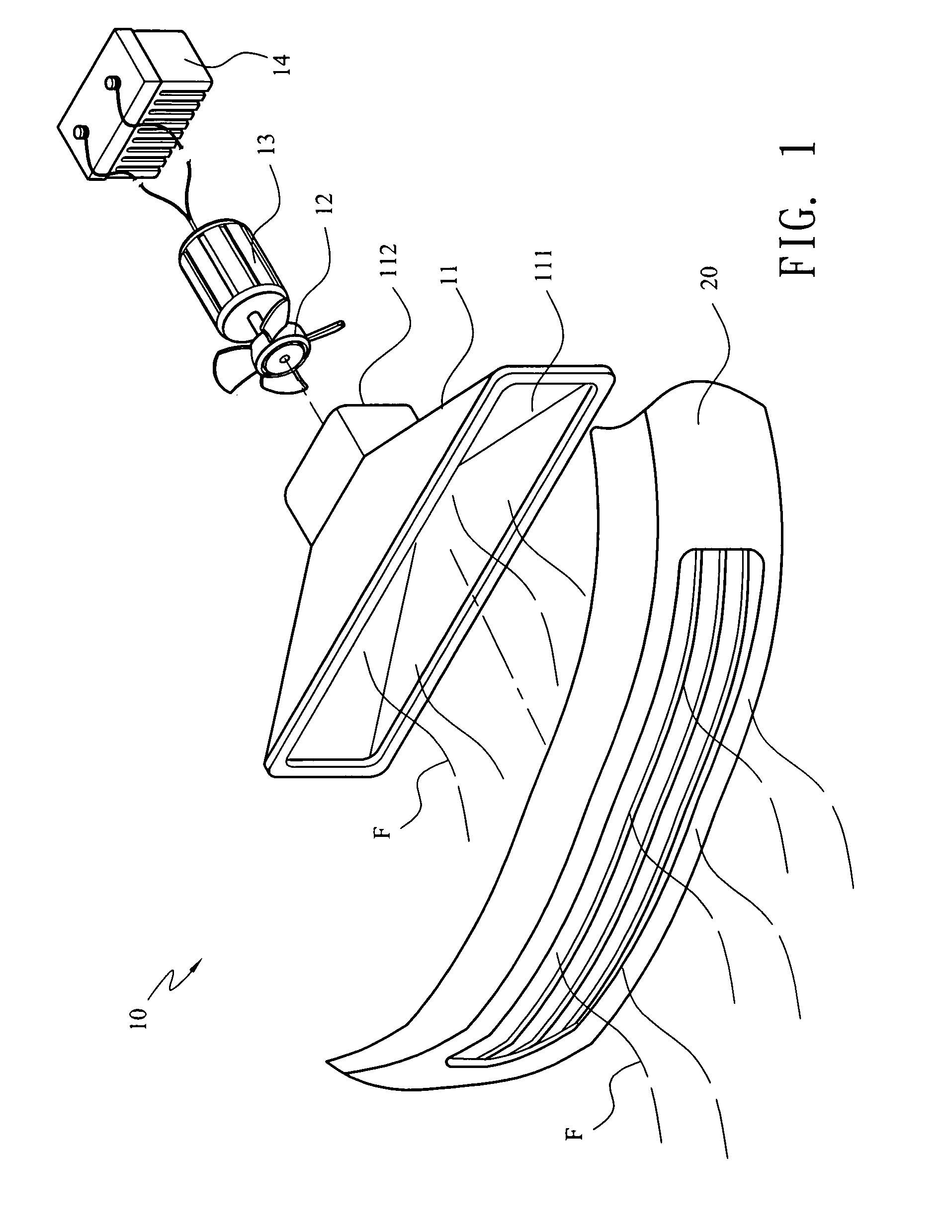
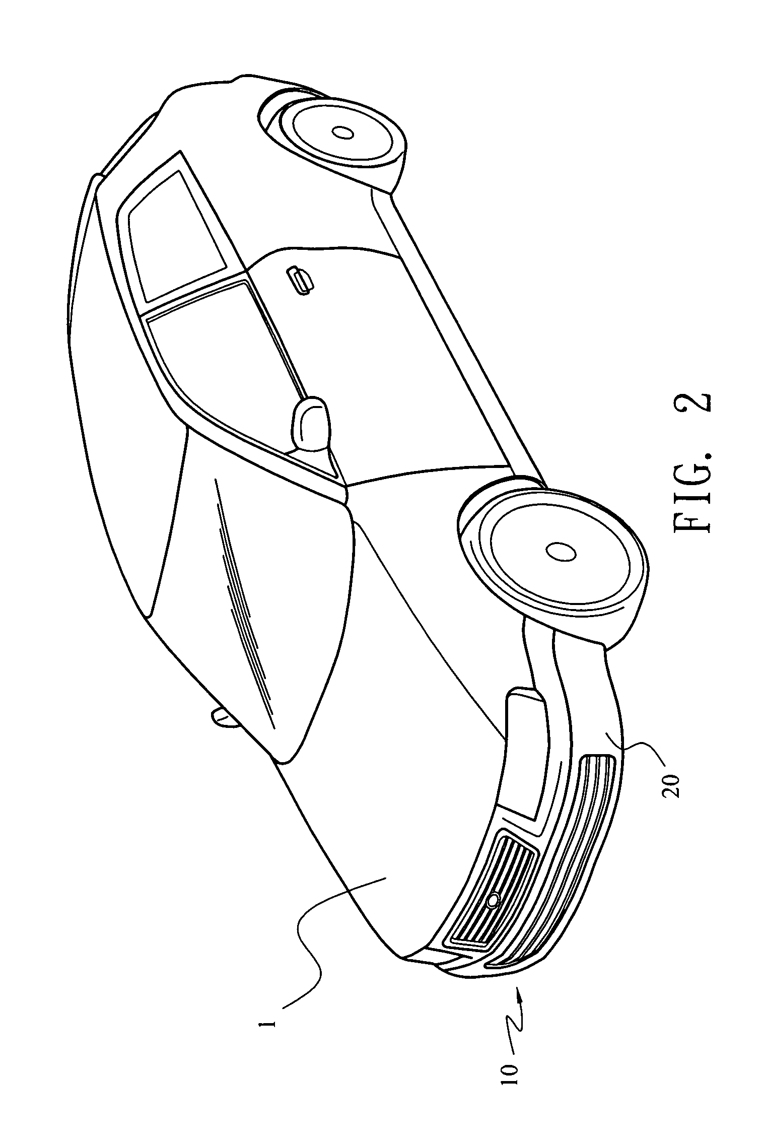
[0018]Referring to FIG. 1 and FIG. 2, the present invention relates to a vehicular wind power generation device. The vehicular wind power generation device 10 provides rechargeable power for a vehicle 1, wherein the vehicle 1 comprises a bumper 20 facing and guiding a windward current F. The vehicular wind power generation device 10 also comprises a wind guiding hood 11, a directing-rotating element 12, a power generator 13, and a power storage unit 14.

[0019]The wind guiding hood 11 comprises at least a wind guiding inlet 111 and at least a wind guiding outlet 112 communicating therewith. The windward area of the wind guiding inlet 111 is greater than that of the wind guiding outlet 112. The wind guiding inlet 111 of the wind guiding hood 11 is connected to the bumper 20 so as to receive the windward current F guided by the bumper 20, and the windward current F is blown out of the wind guiding outlet 112. The directing-rotating element 12 is disposed at the wind guiding outlet 112 o...


PUM


Abstract

A vehicular wind power generation device is provided for a vehicle including a bumper facing and guiding a windward current. The device includes a wind guiding hood with a wind guiding inlet and outlet communicating therewith, a directing-rotating element disposed at the wind guiding outlet, a power generator, and a power storage unit. The windward area of the wind guiding inlet is greater than that of the wind guiding outlet. The wind guiding inlet is connected to the bumper so as to receive the windward current blowing out of the wind guiding outlet, thus allowing the directing-rotating element to receive the windward current. The power generator is connected to the directing-rotating element and the power storage unit. The directing-rotating element is rotated by the windward current blowing toward the directing-rotating element while the vehicle is in motion. Eventually, the power generator generates power for providing rechargeable power for the vehicle.

Description

[0001]This application claims the benefit of Taiwan Patent Application No. 096122958, filed on Jan. 31, 2007, which is hereby incorporated by reference for all purposes as if fully set forth herein.BACKGROUND OF THE INVENTION[0002]1. Field of the Invention[0003]The present invention relates to a vehicular wind power generation device, and more particularly, to an improved vehicular wind power generation device, for generating vehicular rechargeable power, using the wind resulting from a vehicle in motion.[0004]2. Description of the Prior Art[0005]In general, power is generated by combustion of hydrocarbons to drive the engine of a vehicle. However, resources of crude oil have never been scarcer than they are now, and their prices are increasingly high. The greenhouse effect, which arises from decades of consumption of petroleum, and other types of pollution are becoming more serious. Conventional hydrocarbon vehicles are going to use up the earth's resources sooner or later. Last bu...

Claims


Application Information

Patent Timeline
IPC IPC(8): B60K16/00B60L8/00F03D9/02H02J7/14
CPCB60K16/00B60K2016/006F03D9/002F03D9/021B60L8/006Y02E10/725Y02T10/7083Y02T10/90Y02T90/16F05B2240/941F03D9/11F03D9/25Y02E10/728Y02E10/72Y02T10/7072Y02E70/30F03D9/32F03D1/04
Inventor CHEN, TAI-LIANG
Owner YEH YANG CHING
Learn More