Payment Device with Audio and/or Visual Capability and Associated Method

a technology of audio and/or visual capability and payment device, applied in the field of electronic and computer arts, can solve the problems of unnecessary expense, use of batteries in payment device, especially payment card, etc., and achieve the effect of avoiding safety, environmental and/or cost issues

Inactive Publication Date: 2008-07-31
MASTERCARD INT INC
View PDF9 Cites 36 Cited by
  • Summary
  • Abstract
  • Description
  • Claims
  • Application Information

AI Technical Summary

Benefits of technology

[0010]One or more techniques of the present invention can provide one or more of the following substantial beneficial technical effects. These can include, for example, avoiding safety, environmental, and / or cost issues associated with battery-powered devices. In one or more embodiments, tones, jingles, songs, and / or portions of songs or music, and the like, may be provided, for example, from a credit or debit card issuer over a payment network. Today, such networks are typically provisioned to carry only payment data, while one or more embodiments of the invention support the transport of digital audio data directly into the smart card (powered as mentioned above). One such payment network is the CIRRUS® ATM network (registered trademark of MasterCard International Incorporated of Purchase, N.Y.) which could be modified to be able to support transport of such audio data in a fixed or variable format, apparent to the skilled artisan given the teachings herein. In one or more embodiments, the card issuer would provide to the cardholder personalized audio data, which can be changed on demand at the request of one or both parties. If the cardholder has a personal computer (PC) with a smart card reader, audio data can be sent over the Internet to the PC and then to the smart card.

Problems solved by technology

Use of batteries in payment devices, especially payment cards, is believed to be undesirable, as batteries may pose a safety and / or environmental concern due to the presence of harsh chemicals, and may also result in unnecessary expense.

Method used


Image

  • Payment Device with Audio and/or Visual Capability and Associated Method
  • Payment Device with Audio and/or Visual Capability and Associated Method
  • Payment Device with Audio and/or Visual Capability and Associated Method

Examples


Embodiment Construction

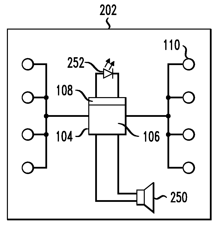
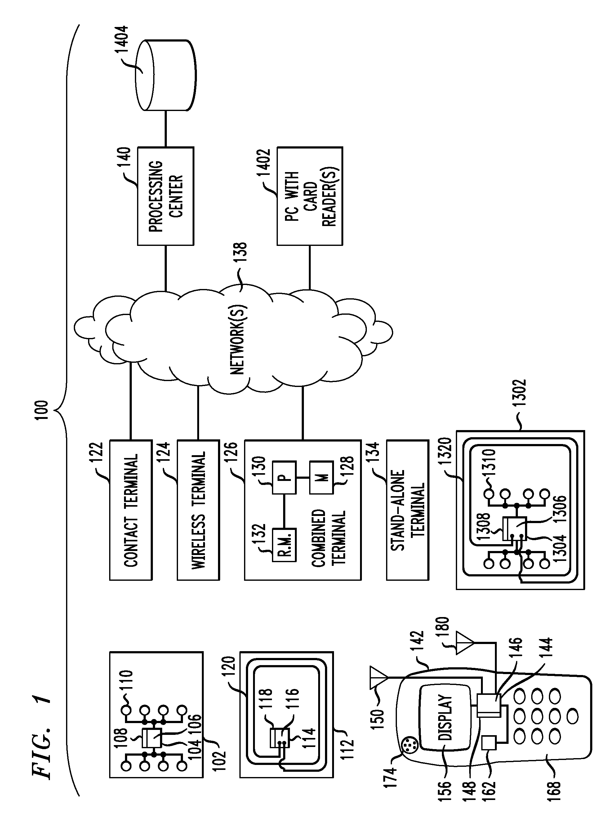
[0018]Attention should now be given to FIG. 1, which depicts an exemplary embodiment of a payment card infrastructure 100, together with various possible components thereof. System 100 can implement inventive techniques, and can interact with inventive payment devices. One type of typical payment device can be a contact device such as card 102. Card 102 can include an integrated circuit (IC) chip 104 having a processor portion 106 and a memory portion 108. A plurality of electrical contacts 110 can be provided for communication purposes. An example of a device similar to card 102, modified according to certain techniques of the invention, will be discussed below in connection with FIG. 2.

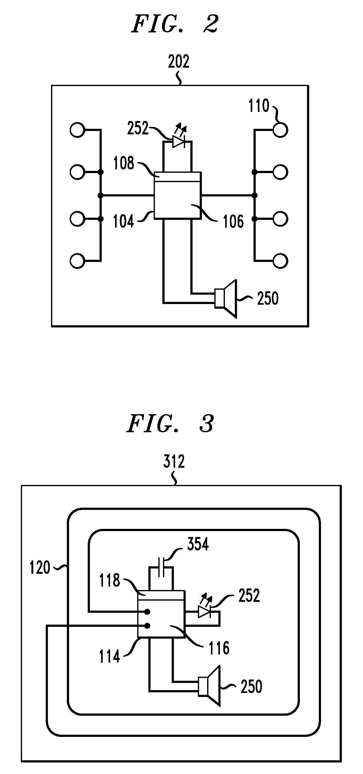
[0019]Infrastructure 100 can also work with a contactless device such as card 112. Card 112 can include an IC chip 114 having a processor portion 116 and a memory portion 118. An antenna 120 can be provided for contactless communication, such as, for example, using radio frequency (RI) electromagnet...


PUM


Abstract

A payment device includes a memory, a processor coupled to the memory, a communications module coupled to the processor and configured to interact with a payment terminal, a sound-producing element coupled to the processor, and an associated body portion. The memory is configured to store at least one representation of at least one sound and the processor is configured to cause the sound-producing element to produce a sound corresponding to the at least one representation of the at least one sound when such representation is stored in the memory, responsive to the communications module interacting with the payment terminal, substantially without usage of a battery on the device Visual stimuli can be employed in addition to or in lieu of sounds. Sounds can be downloaded to devices with or without batteries, as part of a service offering.

Description

CROSS-REFERENCE TO RELATED APPLICATIONS[0001]This patent application claims the benefit of U.S. Provisional Patent Application Ser. No. 60 / 898,220 filed Jan. 30, 2007 and entitled “Payment Device With Audio and / or Visual Capability and Associated Method” of inventors Leland Stanford Englebardt et al. The disclosure of the aforementioned Provisional Patent Application Ser. No. 60 / 898,220 is expressly incorporated herein by reference in its entirety.FIELD OF THE INVENTION[0002]The present invention relates generally to the electronic and computer arts, and, more particularly, to apparatus and methods for electronic payments.BACKGROUND OF THE INVENTION[0003]Electronic payment devices, such as “smart” debit and credit cards, have increased in popularity. These may include “contacted” cards, which have a series of electrical contacts, and are powered by providing voltage to the contacts, as well as “contactless” cards, which employ an antenna coil.[0004]U.S. Pat. No. 6,902,116 of Alan Fi...

Claims


Application Information

Patent Timeline
Patent Type & Authority Applications(United States)
IPC IPC(8): G06K19/067
CPCG06K19/077G06Q20/327G06Q20/32
Inventor ENDLEBARDT, LELAND STANFORDWANKMUELLER, JOHNROBERTS, DAVID A.
Owner MASTERCARD INT INC
Why Eureka
Try Eureka