Transistor with embedded silicon/germanium material on a strained semiconductor on insulator substrate

a technology of strained silicon/germanium material and transistor, which is applied in the direction of semiconductor devices, basic electric elements, electrical appliances, etc., can solve the problems of shrinkage of transistor dimensions and inability of nmos transistors to efficiently contribute to the overall device performance, etc., and achieve the effect of increasing strain transfer and increasing strain transfer

Inactive Publication Date: 2008-07-31
TAIWAN SEMICON MFG CO LTD
View PDF9 Cites 13 Cited by
  • Summary
  • Abstract
  • Description
  • Claims
  • Application Information

AI Technical Summary

Benefits of technology

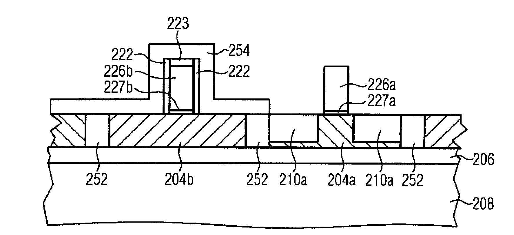
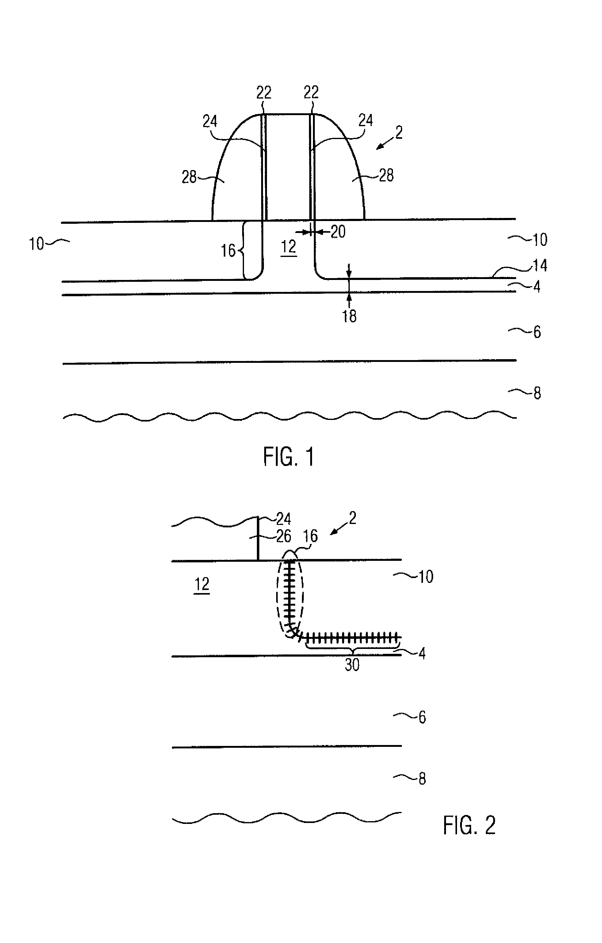
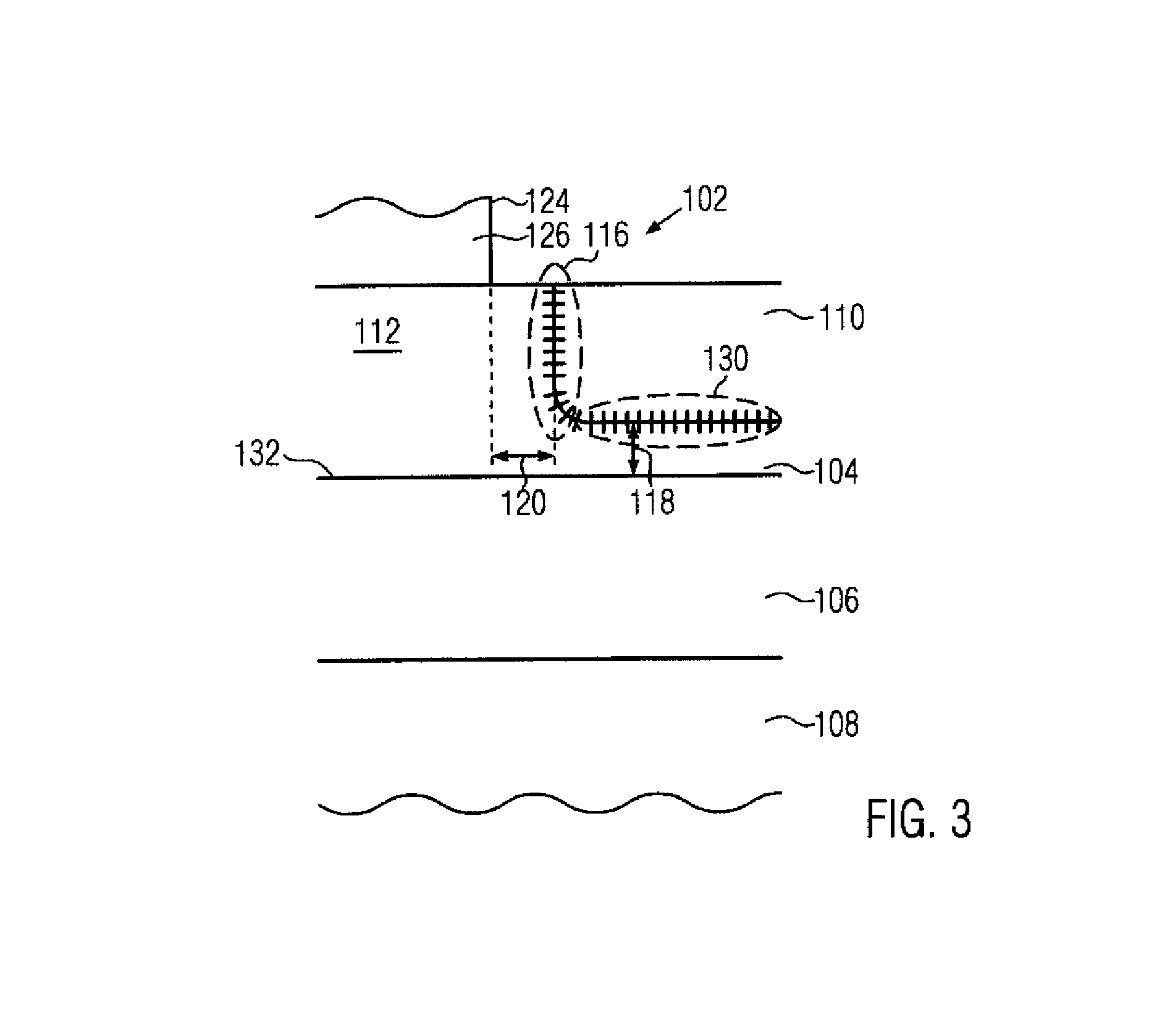
[0012]One illustrative method disclosed herein comprises providing a base comprising a biaxially strained first semiconductor material. The base is then bonded to a substrate. The strained first semiconductor material is then exposed to provide a surface of the strained first semiconductor material, wherein the surface is opposite the substrate. A second semiconductor material is then embedded in the biaxially strained first semiconductor material in a source/drain region of a first transistor, wherein the source/drain regions have a channel region comprising the biaxially strained first semiconductor material therebetween. The first semiconductor material, the biaxial strain and the second semiconductor material are selected such that, compared to an unstrained first semiconductor material, the biaxial strain in the first semiconductor material acts to influence a lattice mismatch at an interface portion between the first se

Problems solved by technology

The continuing shrinkage of the transistor dimensions, however, involves a plurality of issues associated therewith that have to be addressed so as to not unduly offset the advantages obtained by steadily decreasing the channel length of MOS transistors.
However, some mechanisms for obtaining a high channel controllability may also have a negative influence on the charge carrier mobility in the channel region of the transistor, thereby

Method used


Image

  • Transistor with embedded silicon/germanium material on a strained semiconductor on insulator substrate
  • Transistor with embedded silicon/germanium material on a strained semiconductor on insulator substrate
  • Transistor with embedded silicon/germanium material on a strained semiconductor on insulator substrate

Examples


Embodiment Construction

[0022]Various illustrative embodiments of the invention are described below. In the interest of clarity, not all features of an actual implementation are described in this specification. It will of course be appreciated that in the development of any such actual embodiment, numerous implementation-specific decisions must be made to achieve the developers' specific goals, such as compliance with system-related and business-related constraints, which will vary from one implementation to another. Moreover, it will be appreciated that such a development effort might be complex and time-consuming, but would nevertheless be a routine undertaking for those of ordinary skill in the art having the benefit of this disclosure.

[0023]The present subject matter will now be described with reference to the attached figures. Various structures, systems and devices are schematically depicted in the drawings for purposes of explanation only and so as to not obscure the present disclosure with details ...


PUM


Abstract

By combining a respectively adapted lattice mismatch between a first semiconductor material in a channel region and an embedded second semiconductor material in an source/drain region of a transistor, the strain transfer into the channel region is increased. According to one embodiment of the invention, the lattice mismatch may be adapted by a biaxial strain in the first semiconductor material. According to one embodiment, the lattice mismatch may be adjusted by a biaxial strain in the first semiconductor material. In particular, the strain transfer of strain sources including the embedded second semiconductor material as well as a strained overlayer is increased. According to one illustrative embodiment, regions of different biaxial strain may be provided for different transistor types.

Description

BACKGROUND OF THE INVENTION[0001]1. Field of the Invention[0002]Generally, the present disclosure relates to the fabrication of integrated circuits, and, more particularly to the formation of transistors having strained channel regions by using embedded silicon / germanium (Si / Ge) to enhance charge carrier mobility in the channel regions of the transistors.[0003]2. Description of the Related Art[0004]The fabrication of complex integrated circuits requires the provision of a large number of transistor elements, which are used in logic circuits as efficient switches and which represent the dominant circuit element for designing circuits. Generally, a plurality of process technologies are currently practiced, wherein, for complex circuitry, such as micro-processors, storage chips and the like, CMOS technology is currently the most promising approach due to the superior characteristics in view of operating speed and / or power consumption and / or cost efficiency. In CMOS circuits, complement...

Claims


Application Information

Patent Timeline
IPC IPC(8): H01L29/778H01L21/8238
CPCH01L21/76256Y10S438/938H01L21/823814H01L21/823878H01L21/84H01L27/1203H01L29/165H01L29/6653H01L29/66628H01L29/66636H01L29/66742H01L29/7843H01L29/7848H01L29/7849H01L29/78684H01L21/823807
Inventor WEI, ANDYKAMMLER, THORSTENBOSCHKE, ROMANHORSTMANN, MANFRED
Owner TAIWAN SEMICON MFG CO LTD
Why Eureka
Try Eureka