Peripheral layer forming apparatus and method for manufacturing honeycomb structure

a technology of forming apparatus and honeycomb, which is applied in the field of forming apparatus for forming honeycomb and a method for manufacturing honeycomb structure, can solve the problems of soot in exhaust gases discharged from internal combustion engines of vehicles, such as buses and trucks, construction machines and the like, and become a serious problem

Inactive Publication Date: 2008-07-31
IBIDEN CO LTD
View PDF98 Cites 75 Cited by
  • Summary
  • Abstract
  • Description
  • Claims
  • Application Information

AI Technical Summary

Benefits of technology

[0009]The present invention further advantageously provides a method for manufacturing a honeycomb structure that includes molding a ceramic material to manufacture a pillar-shaped honeycomb molded body having a plurality of cells longitudinally disposed parallel to one another with a cell wall therebetween, firing the honeycomb molded body to manufacture a honeycomb fired body, and forming a peripheral layer on a peripheral face of a pillar-shaped honeycomb block including one or a plurality of the honeycomb fired bodies by use of a peripheral layer forming apparatus. The peripheral layer forming apparatus includes supporting members, a peripheral layer forming head having a squeegee with a face, and a material supplying unit that supplies the peripheral layer forming material to the peripheral face. The forming of the peripheral layer includes allowing the supporting members to sandwich the honeycomb block from both sides of an axis direction of the honeycomb block to support the honeycomb block so that an axis of the honeycomb block is maintained in a horizontal direction, allowing the material supplying unit to supply a peripheral layer forming material to the peripheral face, and allowing at least one of the squeegee and the honeycomb block to move so as to maintain a predetermined angle between the face of the squeegee and a virtual face, where the virtual face is defined as a plane that is parallel to the axis of the pillar-shaped member and that is tangential to a contact point on a peripheral face of the pillar-shaped member where the squeegee is configured to contact the pillar-shaped member.

Problems solved by technology

In recent years, particulates such as soot contained in exhaust gases discharged from internal combustion engines of vehicles, such as buses and trucks, construction machines and the like, have become a serious problem as such contaminants are harmful to the environment and the human body.

Method used


Image

  • Peripheral layer forming apparatus and method for manufacturing honeycomb structure
  • Peripheral layer forming apparatus and method for manufacturing honeycomb structure
  • Peripheral layer forming apparatus and method for manufacturing honeycomb structure

Examples


first embodiment

[0060]Referring to the figures, the following description will discuss a first embodiment of the present invention.

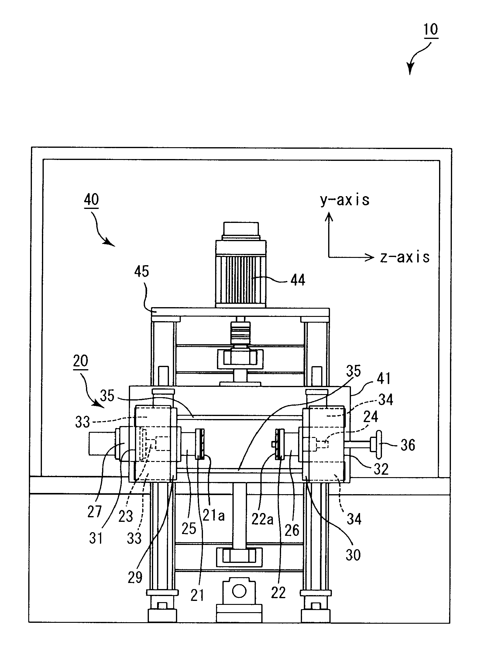
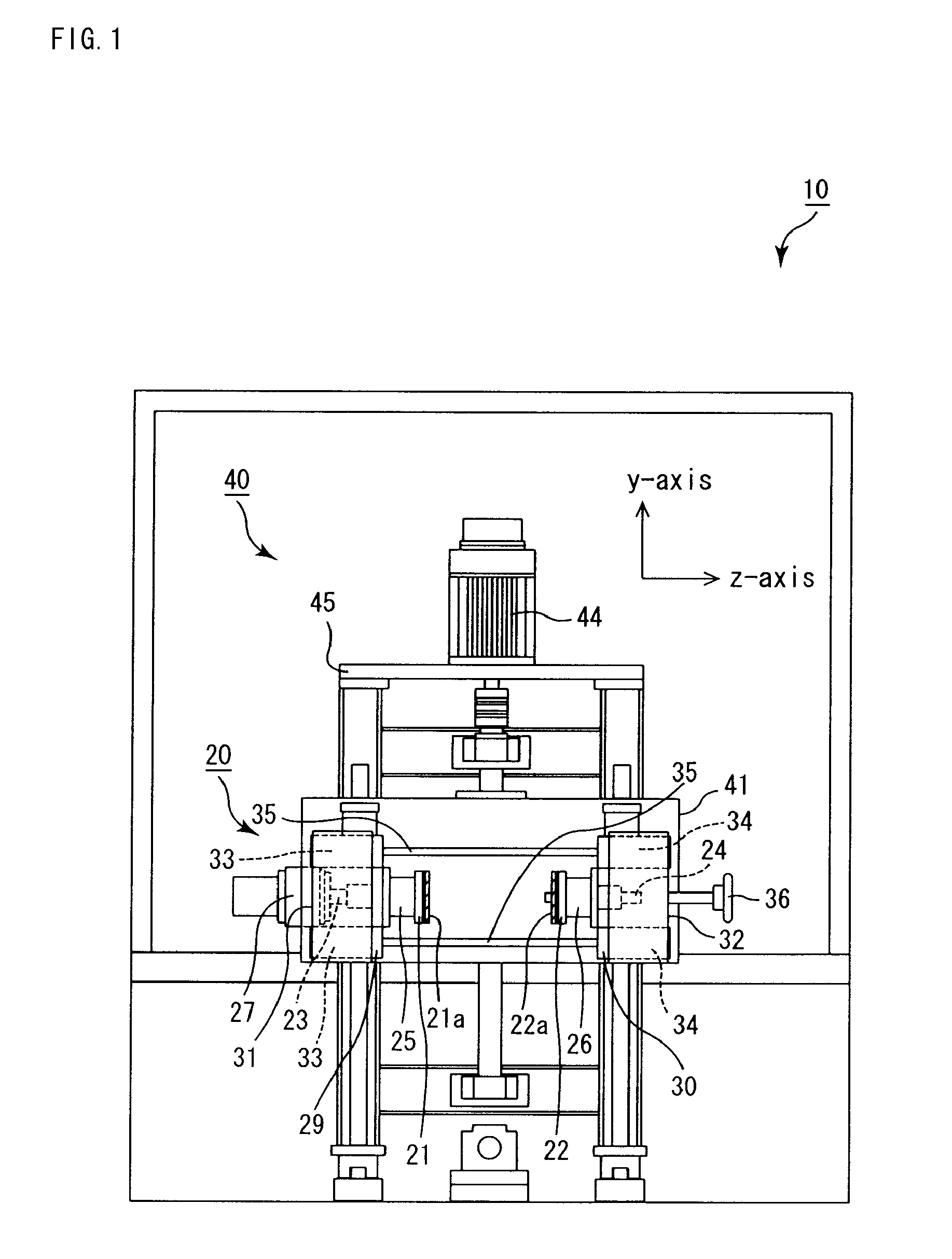
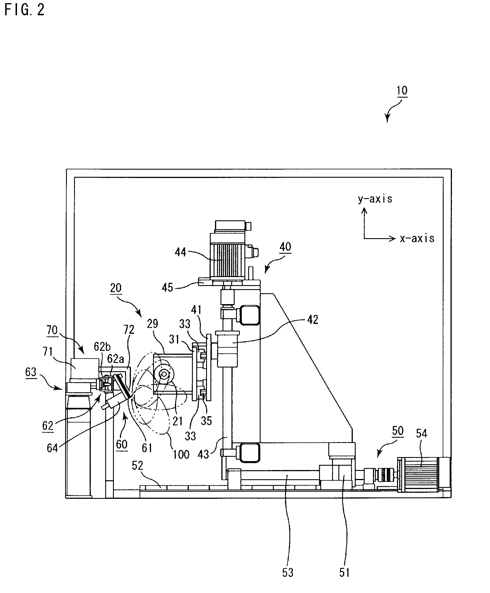
[0061]FIG. 1 is a front view that shows a peripheral layer forming apparatus according to the first embodiment of the present invention, and FIG. 2 is a side face half-cross-sectional view that shows the peripheral layer forming apparatus shown in FIG. 1.

[0062]Here, for ease of understanding of the structure, a peripheral layer forming head and the like are omitted in FIG. 1. Moreover, a supporting member and the like, disposed on the right side of the apparatus shown in FIG. 1, are omitted in FIG. 2.

[0063]A peripheral layer forming apparatus 10 is provided with supporting members 21 and 22, motion control mechanisms (first driving mechanism) 20, 40 and 50, a peripheral layer forming head 60 and a peripheral layer forming material supplying unit 70.

[0064]First, a support and rotation mechanism 20 will be described. The support and rotation mechanism 20, which controls a...

example 1

[0159]Powder mixture was prepared by mixing 250 kg of α-type silicon carbide powder having an average particle diameter of 10 μm, 100 kg of α-type silicon carbide powder having an average particle diameter of 0.5 μm and 30 kg of an organic binder (methyl cellulose).

[0160]Next, a liquid mixture was prepared separately by mixing 22 kg of a lubricant (UNILUB, manufactured by NOF Corp.), 5 kg of a plasticizer (glycerin) and 65 kg of water, and this liquid mixture and the powder mixture were mixed by using a wet mixing machine, so that a wet mixture was prepared.

[0161]Here, the moisture content of the wet mixture thus prepared was 24% by weight.

[0162]Next, this wet mixture was transported to an extrusion-molding machine by using a transporting device and charged into a material charging port of the extrusion-molding machine.

[0163]Here, immediately before the charging into the extrusion-molding machine, the moisture content of the wet mixture was 23.5% by weight.

[0164]Thus, a molded body ...

example 2

[0172]A honeycomb structure was manufactured in the same manner as in Example 1, except that the predetermined angle α was each of the values shown in Table 1.

TABLE 1ReferenceReferenceReferenceReferenceComparativeExample 1Example 2Example 3Example 4Example 1Example 2Example 3Example 4Example 1Angle α30°60°60°60°0°90°60°60°Not constantDiagonal cut-out portionAbsentAbsentPresentPresentAbsentAbsentPresentPresentAbsentAngle β—— 4° 8°—— 0°12°—AppearanceSatis-Satis-Satis-Satis-NonuniformThin, withNonuniformThinChipping onfactoryfactoryfactoryfactoryin thickness,slightin thickness,peripheralwith slightirregularitieswith slightlayer, withirregularitiesirregularitiesirregularitiesSurface roughness8685898510510110392110(Rmax) (μm)Exhaust gas leakage testHardlyHardlyHardly anyHardly anySlight partialSlight partialSlight partialHardly anyAdhesion(adhesion of soot)anyanyadhesionadhesionadhesionadhesionadhesionadhesionover wideadhesionadhesionrangeThickness10.230.180.240.210.270.110.380.200.49of2...


PUM

PropertyMeasurementUnit
angleaaaaaaaaaa
angleaaaaaaaaaa
electricalaaaaaaaaaa

Abstract

A peripheral layer forming apparatus for coating a pillar-shaped member with a peripheral layer. The apparatus includes supporting members configured to sandwich the member from both sides and support the member so that an axis of the member is maintained in a horizontal orientation. A peripheral layer forming head is provided having a squeegee with a face configured to be oriented parallel to the axis. The apparatus is configured to provide the face at a predetermined angle with respect to a virtual face, where the virtual face is defined as a plane that is parallel to the axis of the member and that is tangential to a contact point on a peripheral face of the member where the squeegee is configured to contact the member. The apparatus is configured to maintain the predetermined angle as a peripheral layer is formed on the peripheral face of the member by a movement of at least one of the squeegee and the member.

Description

CROSS-REFERENCE TO RELATED APPLICATIONS[0001]The present application claims priority under 35 U.S.C. § 119 to PCT Application No. PCT / JP2007 / 051287, filed Jan. 26, 2007. The contents of this PCT application are incorporated herein by reference in their entirety.BACKGROUND OF THE INVENTION[0002]1. Field of the Invention[0003]The present invention relates to a peripheral layer forming apparatus and a method for manufacturing a honeycomb structure.[0004]2. Discussion of the Background[0005]In recent years, particulates such as soot contained in exhaust gases discharged from internal combustion engines of vehicles, such as buses and trucks, construction machines and the like, have become a serious problem as such contaminants are harmful to the environment and the human body. For this reason, various particulate filters, which use a honeycomb structure made of porous ceramics to collect particulates in exhaust gases and purify the exhaust gases, have been proposed. Moreover, honeycomb s...

Claims


Application Information

Patent Timeline
Patent Type & Authority Applications(United States)
IPC IPC(8): B29C47/12B29C48/30
CPCB28B19/0038B05C5/0208
Inventor IWATA, SATOSHI
Owner IBIDEN CO LTD
Why Eureka
Try Eureka