Scanning apparatus with heat dissipating ability

Inactive Publication Date: 2008-07-31
LITE ON TECH CORP
View PDF8 Cites 6 Cited by
  • Summary
  • Abstract
  • Description
  • Claims
  • Application Information

AI Technical Summary

Benefits of technology

[0013]The advantage of the present invention is that the light emitting unit is disposed on the supporting portion while the supporting portion extends from an edge of the slit of the cover, such that the scanning light is emitted onto the document after passing through the slit directly or after be reflected, which significantly simplifies the structure of the scanning apparatus. The heat generated by the light emitting unit is directly conducted to the heat dissipating portion through the supporting portion, and thus being dissipated to the air. The surface area of the heat dissipating portion can be determined according to the heat generation rate of the light emitting unit, so as to obtain the require heat dissipating performance, and control the work temperature of the light emitting unit at an optimal temperature.
[0014]Furthermore, the light emitting unit of the present invention can be rapidly positioned on a predetermined position of the cover, in which a

Problems solved by technology

However, a high operating voltage and a high discharge voltage are required to activate the CCFL, so a high voltage driving circuit is required to be disposed in the scanning apparatus for providing a high voltage to drive the CCFL.
Therefore, the cost of the scanning apparatus is increased.
If the temperature of the CCFL increases after the scanning apparatus performs uninterrupted operation, the intensity of the emitted light may also change, and even the spectrum of the light shifts, such that the emitted light is not the ideal white light anymore, and the image scanning quality under the uninterrupted operation of the scanning apparatus is inconsistent.
However, the LEDs generate a large amount of heat during emitting light, such that the application of the LEDs is limited.
The heat generated by the LEDs negatively affects the other components in the scanning apparatus, and the scanning apparatus may be malfunctioned due to the heat generated by the LEDs.
Take the negative effect on LEDs themselves as an illustration, the intensity and the spectrum of the light emitted by the LEDs are varied when the temperature of the LED

Method used


Image

  • Scanning apparatus with heat dissipating ability
  • Scanning apparatus with heat dissipating ability
  • Scanning apparatus with heat dissipating ability

Examples


first embodiment

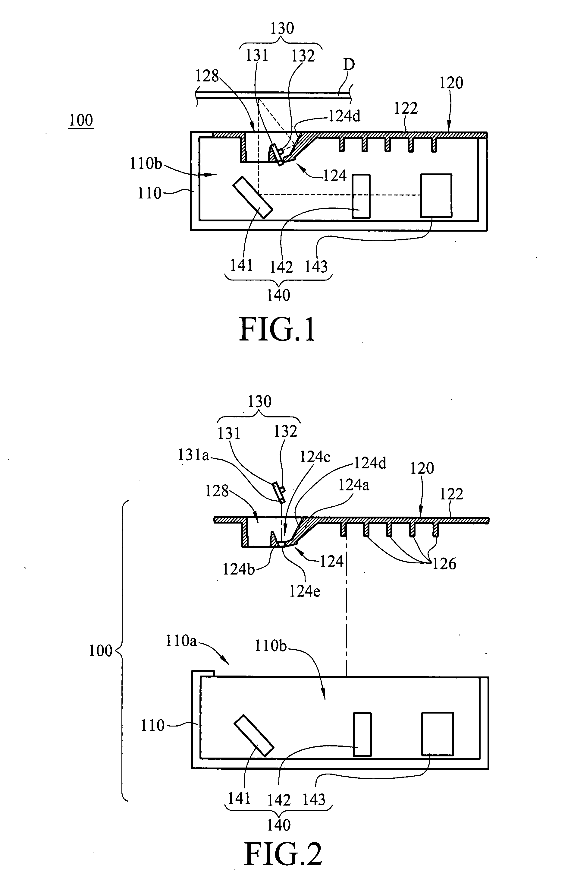
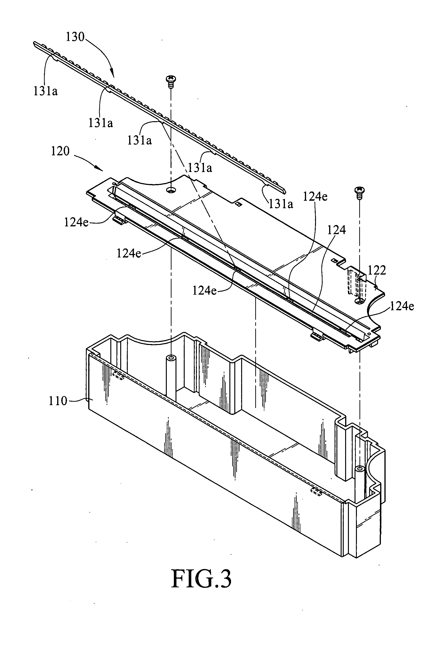
[0023]Referring to FIGS. 1, 2, 3, and 4, a scanning apparatus 100 having heat dissipating ability according to the present invention is provided, for scanning an image of a document D and converting the image to an image data. The scanning apparatus 100 includes a housing 110, a cover 120, a light emitting unit 130, and an image scanning module 140.

[0024]The housing 110 has an opening 110a formed on a top surface thereof, and has a containing space 110b formed therein, wherein the image scanning module 140 is disposed in the containing space 110b of the housing 110.

[0025]The cover 120 has a slit 128, a heat dissipating portion 122, and a supporting portion 124 connected to the heat dissipating portion 122. The supporting portion 124 extends from an edge of the slit 128 of the cover 120 into the containing space 110b of the housing 110, so as to form a recessed supporting space 124c. The light emitting unit 130 has a substrate 131 and a plurality of light emitting elements 132, for e...

second embodiment

[0032]As shown in FIG. 6, a scanning apparatus 100 having heat dissipating ability according to the present invention is provided. The scanning apparatus 100 is provided for scanning an image of a document D, and converting the image to the image data. The scanning apparatus 100 includes a housing 110, a cover 120, a light emitting unit 130, and an image scanning module 140. The cover 120 is fixed on the top surface of the housing 110 to cover the opening thereof, and has a slit 128, a heat dissipating portion 122 made of the thermal conductivity material, and a supporting portion 124 connected to the heat dissipating portion 122. The slit 128 is located corresponding to an edge of the heat dissipating portion 122, and is formed with a long-narrow opening area, for the light to pass through. The supporting portion 124 extends from an edge of the slit 128 of the cover 120 into the containing space 110b of the housing 110. A plurality of concave or convex heat sink structures 126, for...

third embodiment

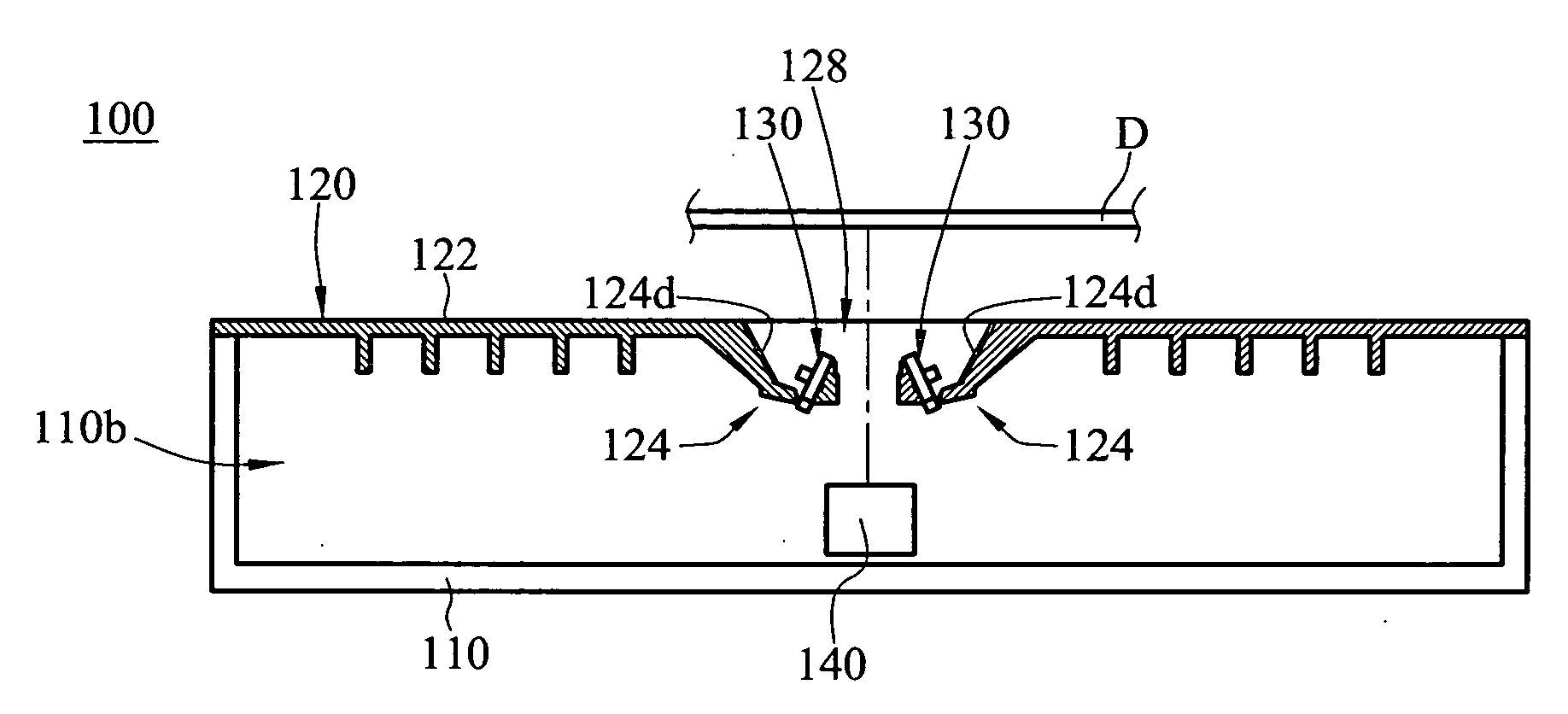
[0034]Referring to FIG. 7, a scanning apparatus 100 according to the present invention is provided. The scanning apparatus 100 is provided for scanning an image of a document D and converting the image to the image data. The scanning apparatus 100 includes a housing 110, a cover 120, two light emitting units 130, and an image scanning module 140. The cover 120 is fixed on the top surface of the housing 110 to cover the opening of the housing 110, and has a slit 128, a heat dissipating portion 122, and two supporting portions 124 connected to the heat dissipating portion 122. The heat dissipating portion 122 is divided by the slit 128 into two regions for performing the heat exchange with the air. The slit 128 is formed with a long-narrow opening area, for the light to pass through. The two supporting portions 124 respectively extend from two opposite edges of the slit 128 of the cover 120, and extend into the containing space 110b of the housing 110. Each supporting portion 124 is p...


PUM


Abstract

A scanning apparatus with heat dissipating ability includes a housing having an opening formed thereon. A cover having a slit, a heating dissipating portion, and supporting portion connected to the heat dissipating portion covers the opening, wherein the supporting portion extends from an edge of the slit into the housing. A light emitting elements is fixed on the supporting portion, for emitting a scanning light through the slit, and the scanning light is reflected as an image light by a document. The image light is converted to image data by an image scanning module. The heat dissipating portion is made of a thermal conductive material to exchange heat with the air, so that heat generated by the light emitting elements is transferred to the heat dissipating portion and the heat is dissipated to the air, the work temperature of the light emitting elements is controlled at an optimal temperature.

Description

CROSS-REFERENCE TO RELATED APPLICATIONS[0001]This non-provisional application claims priority under 35 U.S.C. §119(a) on Patent Application No(s). 096201890 filed in Taiwan, R.O.C. on Jan. 21, 2007, the entire contents of which are hereby incorporated by reference.BACKGROUND OF THE INVENTION[0002]1. Field of Invention[0003]The present invention relates to a scanning apparatus, more particularly to a scanning apparatus with heat dissipating ability.[0004]2. Related Art[0005]A scanning apparatus is composed of a housing, a light emitting unit, and an image scanning module. The light emitting unit and the image scanning module are disposed in the housing. The light emitting unit is provided for emitting a scanning light onto a document through a slit formed on the housing. The scanning light is reflected by the document to form an image light according to the image of the document, and the image light is then received by the image scanning module to be converted to an image data.[0006]...

Claims


Application Information

Patent Timeline
IPC IPC(8): H05K7/20
CPCH05K7/20409
Inventor LEE, TA-YI
Owner LITE ON TECH CORP
Why Eureka
Try Eureka