
Method and system for evaluation of signals received from spatially modulated excitation and emission to accurately determine particle positions and distances

Active Publication Date: 2008-07-31
PALO ALTO RES CENT INC
View PDF99 Cites 74 Cited by
  • Summary
  • Abstract
  • Description
  • Claims
  • Application Information

AI Technical Summary

Problems solved by technology

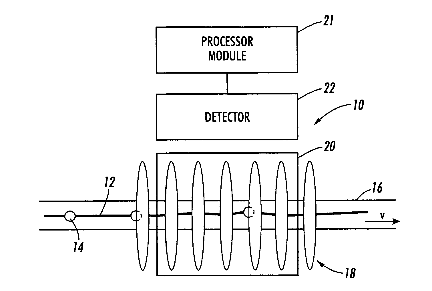
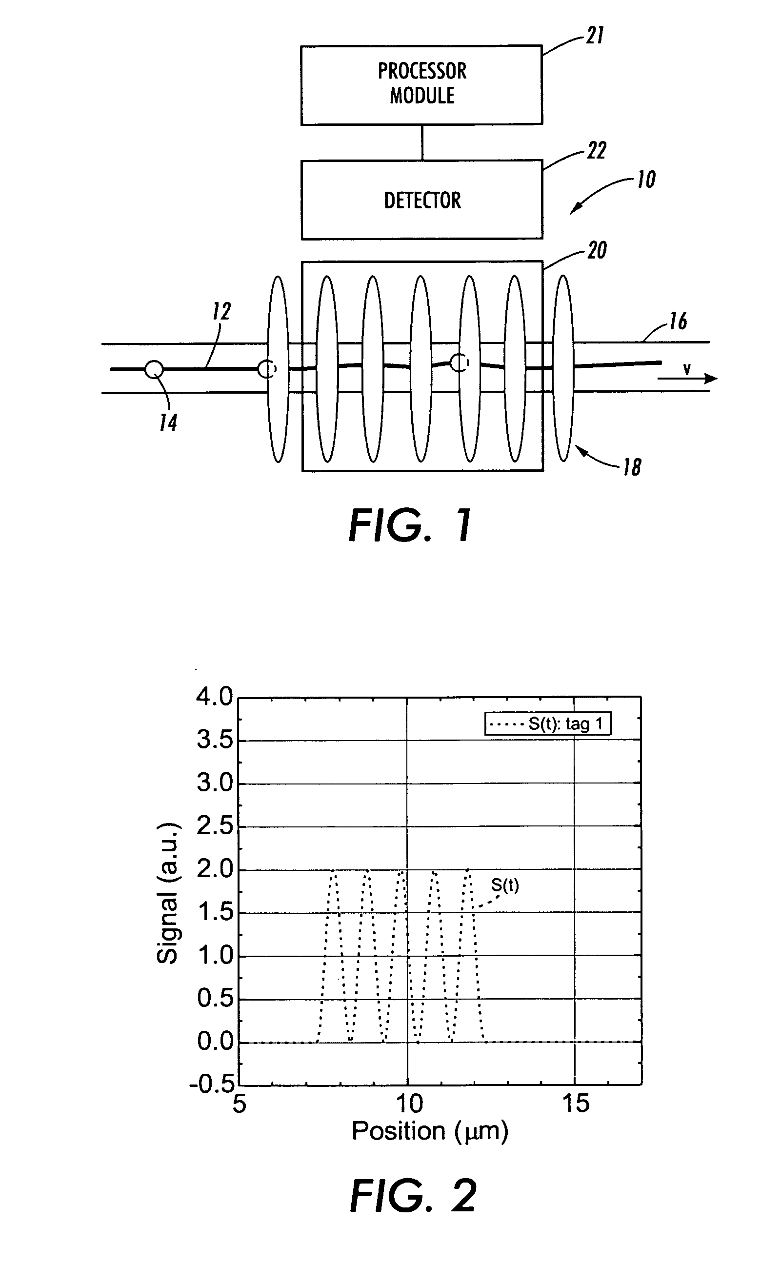
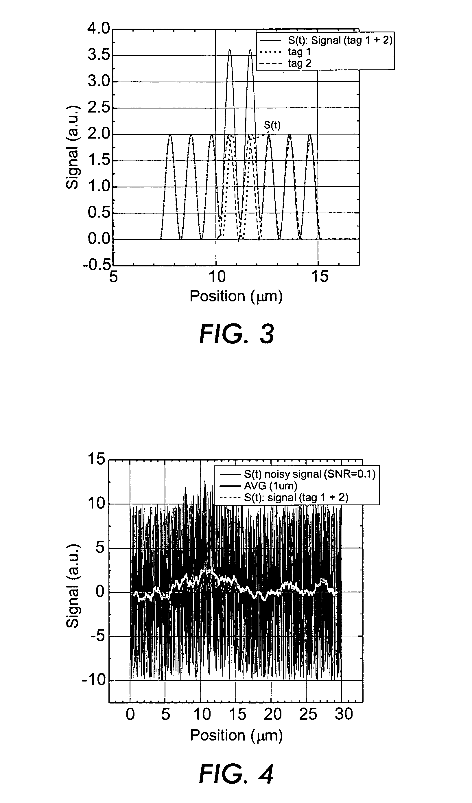
However, determining these positions becomes particularly difficult if two tags 14 are within the detection area at the same time (as in FIG. 3) and / or if the signal is noisy (as in FIG. 4).

Method used


Image

  • Method and system for evaluation of signals received from spatially modulated excitation and emission to accurately determine particle positions and distances
  • Method and system for evaluation of signals received from spatially modulated excitation and emission to accurately determine particle positions and distances
  • Method and system for evaluation of signals received from spatially modulated excitation and emission to accurately determine particle positions and distances

Examples


Embodiment Construction

[0046]According to the presently described embodiments, a method is provided for extracting the position of a particle, e.g., a moving or stationary particle that is excited or is emitting light. The method, in one form, includes, among other techniques, detecting and recording a signal based on, for example, the movement of the particle, a correlating step to eliminate noise and to create a transformed signal, matching or fitting to match the transformed signal to a fit function and extract or determine the position of the particle from the fit function. In one form, at least two particle positions are detected so that the distance between the subject particles and their individual positions can be determined independently.

[0047]In addition, it should be appreciated that particles may be detected and signals may be generated using a variety of systems, including those systems described in U.S. application Ser. No. ______ (Attorney Docket No. 20060254 / XERZ 2 01400), entitled “Method...


PUM


Abstract

A method is provided for extracting the position of a particle, e.g., a moving or stationary particle that is excited or is emitting light. The method includes, among other steps, detecting and recording a signal based on, for example, the movement of the particle, a correlation step to eliminate noise and to create a transformed signal, a matching or fitting step to match the transformed signal to a fit function and an extracting or determining step to determine the position of the particle from the fit function. In one form, at least two particle positions are detected so that the distance between the subject particles can be determined.

Description

CROSS REFERENCE TO RELATED PATENTS AND APPLICATIONS[0001]This application is related to U.S. application Ser. No. ______ (Attorney Docket No. 20060254 / XERZ 2 01400), entitled “Method and System Implementing Spatially Modulated Excitation or Emission for Particle Characterization with Enhanced Sensitivity,” filed on even date herewith.BACKGROUND[0002]There is a desire to detect the precise location and / or distance between particles on a micro-scale. One example of this resides in the use of fluorescent tags on linearized DNA strings based on a spatially modulated excitation. A system and method for detecting such particles or tags is described in U.S. application Ser. No. ______ (Attorney Docket No. 20060254 / XERZ 2 01400), entitled “Method and System Implementing Spatially Modulated Excitation or Emission for Particle Characterization with Enhanced Sensitivity,” filed on even date herewith and incorporated herein by reference.[0003]In an example of the cited application above, with r...

Claims


Application Information

Patent Timeline
IPC IPC(8): G06F15/00G16B5/00
CPCG01N21/6408G01N2015/1486G01N2015/1075G01N21/6458G16H50/20G16B5/00G01N2015/1027G06F2111/10
Inventor BASSLER, MICHAELKIESEL, PETERSCHMIDT, OLIVER
Owner PALO ALTO RES CENT INC
Learn More