
Continuous stroke pneumatic tool with ball valve

Active Publication Date: 2008-08-07
POWER TECH NORTH AMERICA LLC
View PDF19 Cites 4 Cited by
  • Summary
  • Abstract
  • Description
  • Claims
  • Application Information

AI Technical Summary

Benefits of technology

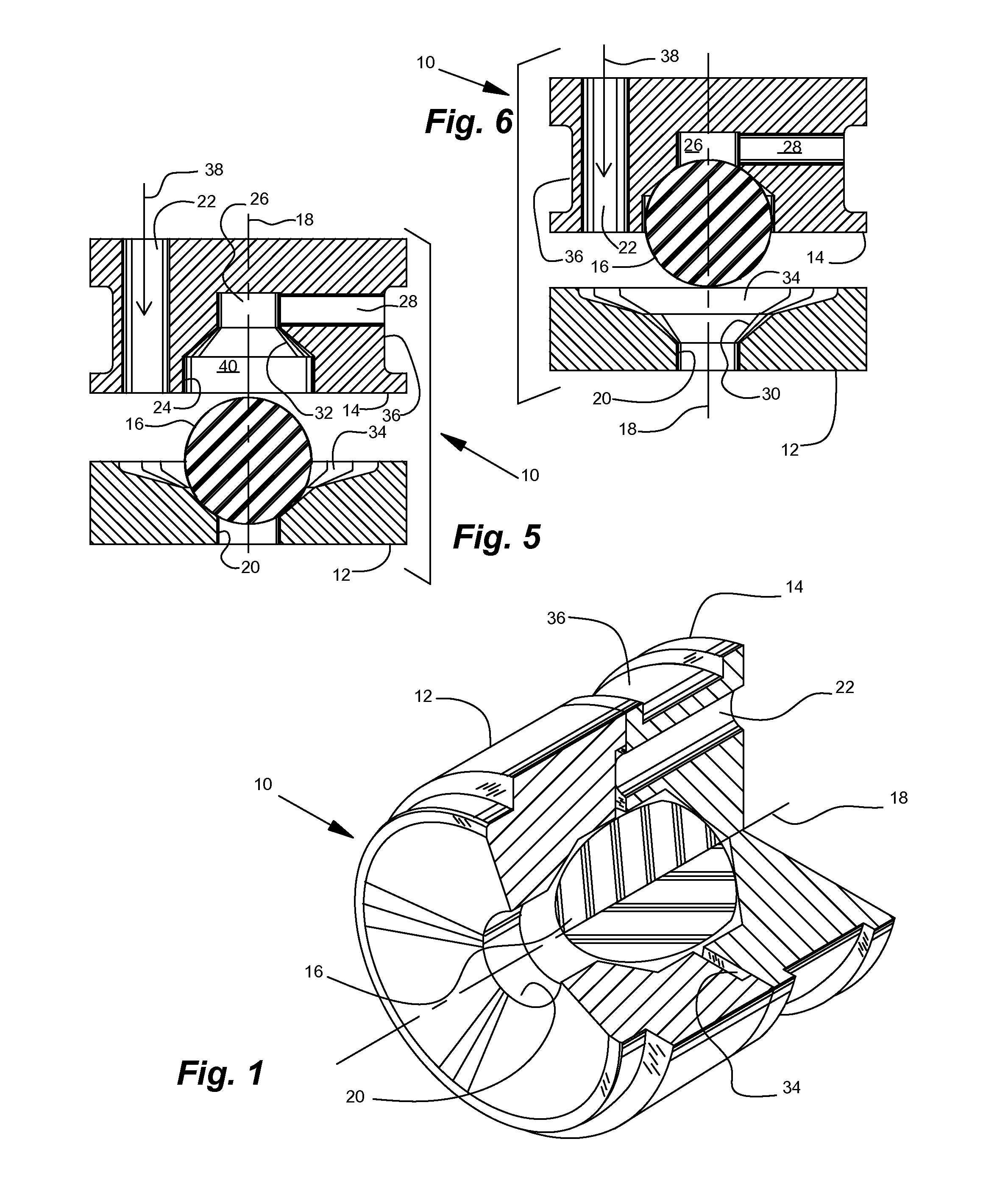
[0023]The valve ball element may be hollow or solid, and it may be composed of the same or different materials throughout. The valve ball element is substantially spherical and free-floating within the valve chamber so that it will rotate freely and generally present a different location (generally a line) for sealing contact with the respective concave generally conical surfaces on substantially every stroke. The ball valve element is afforded a small amount of lateral movement as it moves longitudinally between the respective concave generally conical surfaces. Wear of the valve ball element is thus distributed over the entire surface, and any foreign particles or excess lubricant that gets into the ball valve assembly will be quickly dislodged by the free-floating motion of the valve ball element, or the flow of gas through the ball valve assembly, or both.
[0027]The valve ball element is free to move in more than one plane, allowing it to break any “sticking” between surfaces. The lack of close fitting parts in embodiments allows the free flow of any oils or lubricants that may be present. In certain embodiments, the ball valve assembly itself does not require any form of lubrication. According to certain embodiments, the valve ball elements inherently exhibit high resistance to wear and have a high tensile strength.

Problems solved by technology

A major shortcoming of typical prior art devices and methods is that the required close tolerances within the metal valves made them expensive to make and maintain, and limited their reliability.
The prior valves generally could not self-compensate for wear or blockages, so frequent maintenance and replacement were required.
The machined parts occasionally became self magnetized, which interfered with the operation of the valves.
The steel that was typically used for the valve components was subject to corrosion.
Any dirt, metallic particles, or other debris tended to interfere with the operation of the valves.
Even excessive lubricant could cause the valve parts to become sticky and move erratically.
Pneumatic tools must often operate in very harsh weather.
Any moisture in the valve components tended to cause the valves to freeze or otherwise malfunction.
In general, these prior valves were prone to fail due to conditions frequently encountered during use.
The tight tolerances between diameters and faces of prior devices often trapped this moisture, particularly when the tool was idle for a while.
This frequently caused the prior valves to stick in one position.
Due to the moisture present in compressed air systems, in severe weather conditions or prolonged continuous operation of these types of tools, it was not unusual for the water present to freeze and prevent the tool from functioning.
Sometimes similar metals tend to magnetize themselves as the components rub together, giving erratic operation of the valve.
These gaps were susceptible to causing malfunctions when any debris was ingested into the tool.
This caused the valve to jam or leak air past the surfaces that are not closed.
If too much lubricating oil was administered to the prior tools, the excess oil tended to “glue” close fitting moving parts together, especially at lower temperatures.
Metal to metal contact eventually caused wear on one or more components due to the friction between parts.
Eventually the prior parts wore to the point where the tool would not operate efficiently.
The same surfaces in the prior valves were in contact with each other all the time, inducing wear at specific locations.
These valves often required expensive manufacturing operations, such as grinding, to achieve the tight tolerances that were required.
Without a tight seal, the valve would be inefficient or inoperative depending on how much leakage occurs.

Method used


Image

  • Continuous stroke pneumatic tool with ball valve
  • Continuous stroke pneumatic tool with ball valve
  • Continuous stroke pneumatic tool with ball valve

Examples


Embodiment Construction

[0046]Referring now to the drawings wherein like reference numerals designate identical or corresponding parts throughout the several views. It is to be understood that the drawings are diagrammatic and schematic representations of various embodiments, and are not to be construed as limiting in any way. The use of words and phrases herein with reference to specific embodiments is not intended to limit the meanings of such words and phrases to those specific embodiments. Words and phrases herein are intended to have their ordinary meanings, unless a specific definition is set forth at length herein.

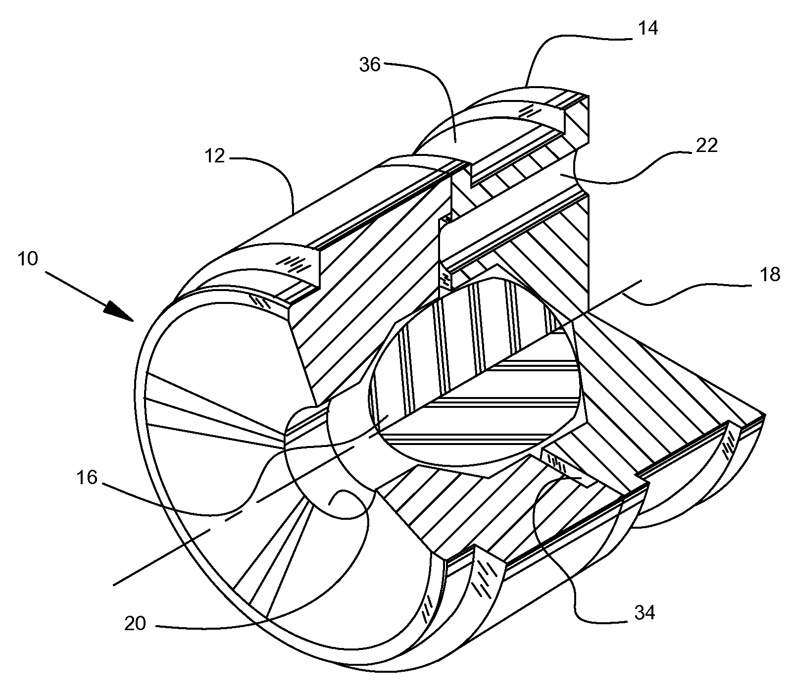
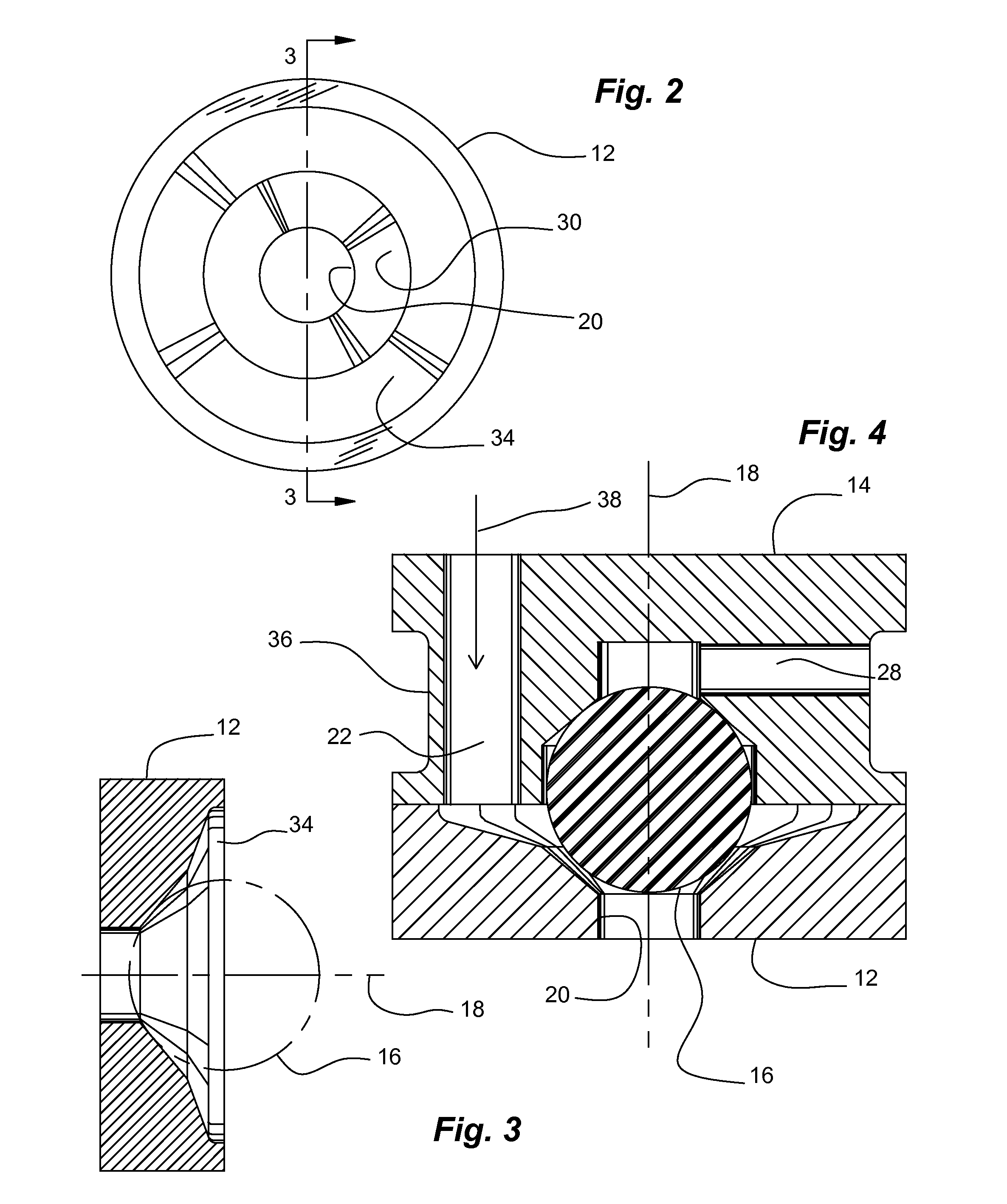
[0047]Referring particularly to the drawings, there is illustrated generally at 10 an embodiment of a ball valve assembly. The ball valve assembly 10 includes a lower valve seat member 12, an upper valve seat member 14, and a valve ball element 16. The components of the ball valve assembly are assembled generally along a longitudinal axis 18. Lower valve seat member 12 includes a power str...


PUM

PropertyMeasurementUnit
Lengthaaaaaaaaaa
Flow rateaaaaaaaaaa
Magnetismaaaaaaaaaa

Abstract

A ball valve assembly for use as a control valve for controlling the flow of gas through a continuous stroke pneumatic tool. The valving element is generally spherical and non-magnetizable. The generally spherical valving element is loosely confined between two concave generally conical surfaces, which are provided on valve seat members. The concave generally conical surfaces are opposed to one another to define a valve chamber therebetween. Sufficient clearance is provided so the generally spherical valving element is free to roll and tumble as it moves in the valve chamber between the concave generally conical surfaces. This allows the ball valve assembly to be self purging of excess lubricant, dust, and the like. Wear is distributed over the entire generally spherical surface of the valving element. The loose confinement is also sufficient to provide a relatively large cross-section of gas passageway through the control valve assembly. The two valve seat members are suitably ported to permit the ball valve assembly to be used as a drop-in replacement for prior pneumatic tool control valves.

Description

RELATED APPLICATIONS[0001]This application claims the benefit of U.S. Provisional Application No. 60 / 899,768, filed Feb. 5, 2007.BACKGROUND OF THE INVENTION[0002]1. Field of the Invention[0003]The present invention relates in general to valving methods and devices for controlling the flow of air in a pneumatic tool, and, more particularly, embodiments of the present invention relate to continuous stroke pneumatic tools in which a ball valve is incorporated in their pneumatic circuits.[0004]2. Description of the Prior Art[0005]Typical continuous stroke pneumatic tools include, for example, jackhammers, impact wrenches, scrappers, files, rasps, riveting guns, rotary hammers, chipping hammers, and the like. These tools generally incorporate a pneumatic circuit, which allows air or other pressurized gas to cause the tools to perform their intended function.[0006]Pneumatic circuits in continuous stroke pneumatic tools typically include a valving mechanism to control the flow of pressuriz...

Claims


Application Information

Patent Timeline
IPC IPC(8): F16K1/38
CPCB25D9/16F16K11/056F16K7/20F16K27/0245
Inventor HALL, ANDREW
Owner POWER TECH NORTH AMERICA LLC
Learn More