[0017]After the joining, according to the invention a positive and nonpositive connection of the gear rim packet and return ring can be achieved by calking on the outside of the tooth tips. The thin-walled connecting struts can be pressed at least in some regions between the wedgelike contact elements of the return ring into an outer indentation of the tooth tips, and as a result the wedgelike contact elements are pulled practically automatically by positive and nonpositive engagement against the corresponding faces of the tooth tips. During the calking, the teeth on the rotor side, that is, on the inside
diameter of the gear rim packet, can favorably be braced by a securing means, such as a mandrel.
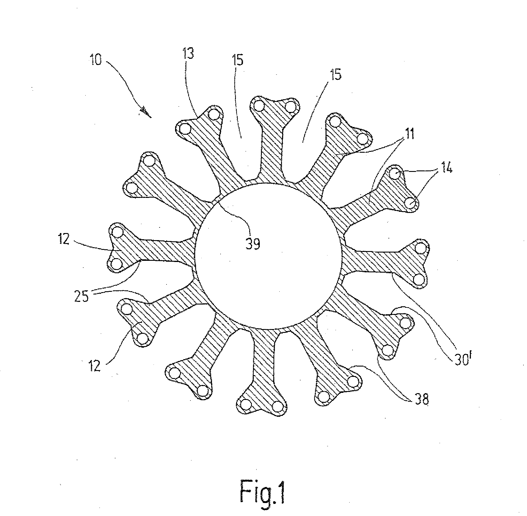
[0011]The DC machine of the invention includes a stator with a winding
assembly and with a rotor; the stator includes a gear rim, with radially outward-extending tooth tips, and a return ring.
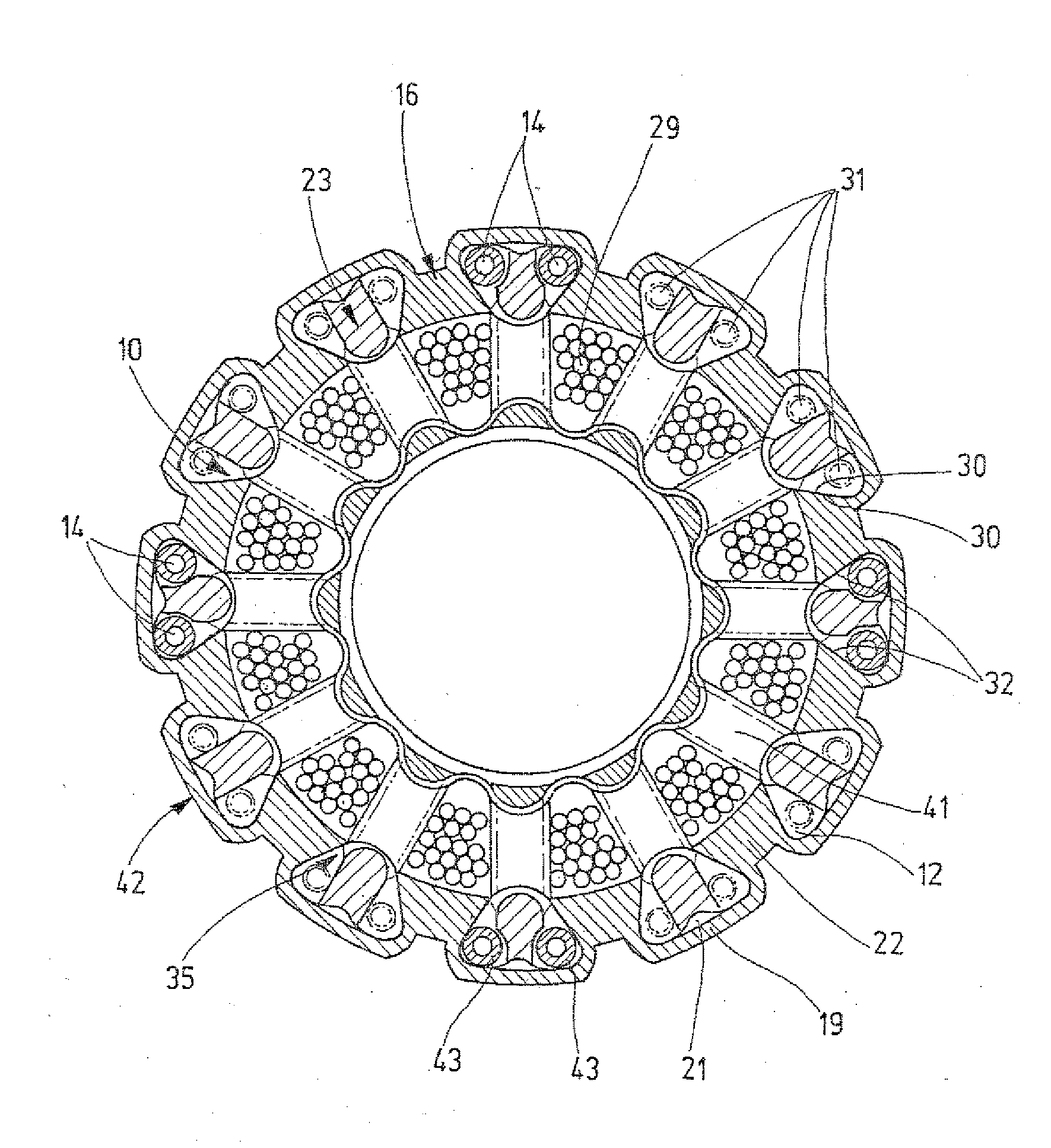
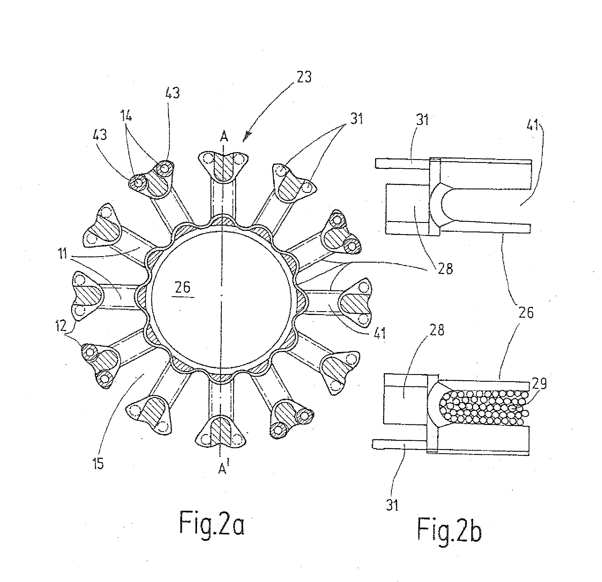
[0015]Preferably, contact faces corresponding with one another of the return ring and of the tooth tips are formed as the connecting means between the two packets. On one contact face, formed by connecting struts of the return ring, corresponding contact faces of the tooth tips of the gear rim can be embodied. It may be provided that contact elements, embodied as adapters, of wedgelike cross section are disposed between the connecting struts of the return ring. Because of the special shaping of the tooth tips and of the return ring, a positive and nonpositive connection can be produced.
[0012]In a favorable embodiment, the connecting means for making a positive and nonpositive connection between the tooth tips of the gear rim and the return ring are deformable. In a further favorable feature, the gear rim and the return ring can be joined into one another without force before a positive and nonpositive connection is made.
[0014]A return ring packet of the invention includes at least one return ring, which is formed of an annular body having radially inward-pointing contact elements that widen in wedgelike fashion toward the inside, and the
contact element form undercuts.
[0014]A return ring packet of the invention includes at least one return ring, which is formed of an annular body having radially inward-pointing contact elements that widen in wedgelike fashion toward the inside, and the
contact element form undercuts.
[0015]Preferably, contact faces corresponding with one another of the return ring and of the tooth tips are formed as the connecting means between the two packets. On one contact face, formed by connecting struts of the return ring, corresponding contact faces of the tooth tips of the gear rim can be embodied. It may be provided that contact elements, embodied as adapters, of wedgelike cross section are disposed between the connecting struts of the return ring. Because of the special shaping of the tooth tips and of the return ring, a positive and nonpositive connection can be produced.
[0019]Especially preferably, the connecting means may be embodied as clamping means, for instance in the form of steel wires or pins that are disposed in at least some regions in the outer indentations in the tooth tips. In the production method of the invention, the clamping means can be press-fitted in between the connecting struts of the return ring and the outer indentation in the tooth tips. On being pressed in, the thin-walled connecting struts are pressed outward and deformed elastically, causing the corresponding faces of the tooth tips and of the return ring to be pulled toward one another. Since the connecting struts are braced on the outside of the tooth tips via the press-fitted pins, advantageously no mechanical stresses in the connection of the teeth toward the rotor are created. These teeth can be favorably separated after joining without problems, either mechanically, for instance with a hollow needle, or electrochemically, for instance using an ECM process, and this disconnection contributes to improving the
magnetic flux course.
[0017]After the joining, according to the invention a positive and nonpositive connection of the gear rim packet and return ring can be achieved by calking on the outside of the tooth tips. The thin-walled connecting struts can be pressed at least in some regions between the wedgelike contact elements of the return ring into an outer indentation of the tooth tips, and as a result the wedgelike contact elements are pulled practically automatically by positive and nonpositive engagement against the corresponding faces of the tooth tips. During the calking, the teeth on the rotor side, that is, on the inside
diameter of the gear rim packet, can favorably be braced by a securing means, such as a mandrel.
[0019]Especially preferably, the connecting means may be embodied as clamping means, for instance in the form of steel wires or pins that are disposed in at least some regions in the outer indentations in the tooth tips. In the production method of the invention, the clamping means can be press-fitted in between the connecting struts of the return ring and the outer indentation in the tooth tips. On being pressed in, the thin-walled connecting struts are pressed outward and deformed elastically, causing the corresponding faces of the tooth tips and of the return ring to be pulled toward one another. Since the connecting struts are braced on the outside of the tooth tips via the press-fitted pins, advantageously no mechanical stresses in the connection of the teeth toward the rotor are created. These teeth can be favorably separated after joining without problems, either mechanically, for instance with a hollow needle, or electrochemically, for instance using an ECM process, and this disconnection contributes to improving the
magnetic flux course.
[0024]The top pieces expediently separate the stator lamination packet from the winding. Preferably, the top pieces protrude at least partway into the slots located between the teeth of the gear rim and serve to guide the winding wires in the slots from one slot to the next. For fixation and adjustment of the top pieces in the stator lamination packet, the top pieces may be provided with pegs, which are pressed into stamped holes in the outer tooth tips of the gear rim packet. The pegs may be provided with notches, for better connection to the gear rim packet. After being wound, the top pieces are expediently additionally held mechanically on the stator by the winding. To further improve the
electrical installation and
mechanical stability, the wound stator packet can be coated, for instance by immersion or dripping onto the winding head.
[0021]One top piece is advantageously disposed on each of the free ends of the stator. In the DC machine, one receiving opening for receiving a rotor bearing is provided in each top piece according to the invention. Because of the special embodiment of the top pieces, which makes it possible to dispose the rotor bearings inside the winding head, a substantial cost and structural space
advantage is gained over the known EC motors, in which a separate housing, for instance of die-cast aluminum, is needed for receiving and supporting the rotor in order to insert the wound stator into it or to provide receptacles for supporting the rotor. By receiving the rotor bearings in the top pieces according to the invention, a very compact design of the DC machine is advantageously made possible, since the rotor bearings can be disposed directly on the rotor lamination packet on the shaft. This has the
advantage that forces acting on the bearings are absorbed over the shortest distances, and imbalances can be intercepted in the best possible way. Since the top piece can be received with its pegs directly by the stator packet, the rotor shaft is optimally adjusted to the
axis of symmetry of the stator packet. The deviation of the rotor shaft from its optimal position in the
axis of symmetry of the stator is favorably markedly less, compared to supporting the rotor shaft in a housing shell in which the stator is received. The additional tolerance of the housing and stator must be compensated for by a larger air gap between the stator and rotor, which adversely affects the magnetic properties. For instance, the maximum attainable torque of the machine is reduced because of the enlargement of the air gap between the stator and the rotor.
[0024]The top pieces expediently separate the stator lamination packet from the winding. Preferably, the top pieces protrude at least partway into the slots located between the teeth of the gear rim and serve to guide the winding wires in the slots from one slot to the next. For fixation and adjustment of the top pieces in the stator lamination packet, the top pieces may be provided with pegs, which are pressed into stamped holes in the outer tooth tips of the gear rim packet. The pegs may be provided with notches, for better connection to the gear rim packet. After being wound, the top pieces are expediently additionally held mechanically on the stator by the winding. To further improve the
electrical installation and
mechanical stability, the wound stator packet can be coated, for instance by immersion or dripping onto the winding head.
[0023]The top pieces are preferably formed of electrically and magnetically nonconductive material, for instance a high-grade
thermoplastic such as polyphenylene
sulfide, also known by the
trademark Fortron. By means of this material,
eddy current losses are advantageously avoided. Especially preferably, the top pieces have rounded edges, to prevent damage to the paint insulation of the winding wires.
[0024]The top pieces expediently separate the stator lamination packet from the winding. Preferably, the top pieces protrude at least partway into the slots located between the teeth of the gear rim and serve to guide the winding wires in the slots from one slot to the next. For fixation and adjustment of the top pieces in the stator lamination packet, the top pieces may be provided with pegs, which are pressed into stamped holes in the outer tooth tips of the gear rim packet. The pegs may be provided with notches, for better connection to the gear rim packet. After being wound, the top pieces are expediently additionally held mechanically on the stator by the winding. To further improve the
electrical installation and
mechanical stability, the wound stator packet can be coated, for instance by immersion or dripping onto the winding head.
[0025]Instead of pegs of the top piece, sometimes mechanical connecting elements such as rivets, screws, and the like may be placed in the stamped holes in the tooth tips, in order to permanently fix the gear rim packet. Further stamped holes for connecting elements may be provided on the outside of the wedgelike contact elements of the return lamination packet. The return lamination packet may be welded as usual, including in the outer region, to the contact elements for the sake of mechanical fixation.

