Vacuum processing apparatus and method, and storage medium for executing the method

a technology of vacuum processing and storage medium, applied in the field of vacuum processing, can solve the problems of deteriorating transfer throughput, large load, and wafer misalignment, and achieve the effects of reducing load on the first and second transfer arms, high alignment accuracy, and enhanced throughpu

Active Publication Date: 2008-08-07
TOKYO ELECTRON LTD
View PDF3 Cites 31 Cited by
  • Summary
  • Abstract
  • Description
  • Claims
  • Application Information

AI Technical Summary

Benefits of technology

[0018]In accordance with the present disclosure described above, the wafer is loaded on the rotary stage in the preliminary vacuum chamber by the first transfer arm under a normal pressure atmosphere, and the position data acquiring unit obtains the position data of the peripheral portion of the wafer mounted on the rotary stage. Then, based on this position data, an alignment of the direction of the wafer is carried out. Then, the second transfer arm in the vacuum transfer chamber conveys the wafer from the rotary stage into the mounting member inside the vacuum processing chamber, while performing an alignment of the center of the wafer. Therefore, the first and second transfer arms are allowed to have a small number of access positions, so that loads upon the first and second transfer arms can be reduced. As a consequence, a throughput can be enhanced. Besides, since the wafer whose center and direction have been adjusted is directly conveyed into the vacuum processing chamber after taken out from the preliminary vacuum chamber by the second transfer arm, it is possible to transfer the wafer into the vacuum processing chamber with a high alignment accuracy.

Problems solved by technology

Thus, the first transfer arm 12 suffers a great load, and a transfer throughput is deteriorated.
Therefore, there is a high likelihood that a misalignment of the wafer would take place while the wafer is being transferred, so it is apprehended that alignment accuracy of the wafer may be deteriorated when the wafer is conveyed into the vacuum processing chamber 16.
Thus, as in the case of installing the position alignment mechanism in the atmospheric transfer area, a deterioration of a throughput of the apparatus is inevitable.
However, Patent Reference 1 is not conceived or adapted to solve the above-mentioned problems.

Method used


Image

  • Vacuum processing apparatus and method, and storage medium for executing the method
  • Vacuum processing apparatus and method, and storage medium for executing the method
  • Vacuum processing apparatus and method, and storage medium for executing the method

Examples


Embodiment Construction

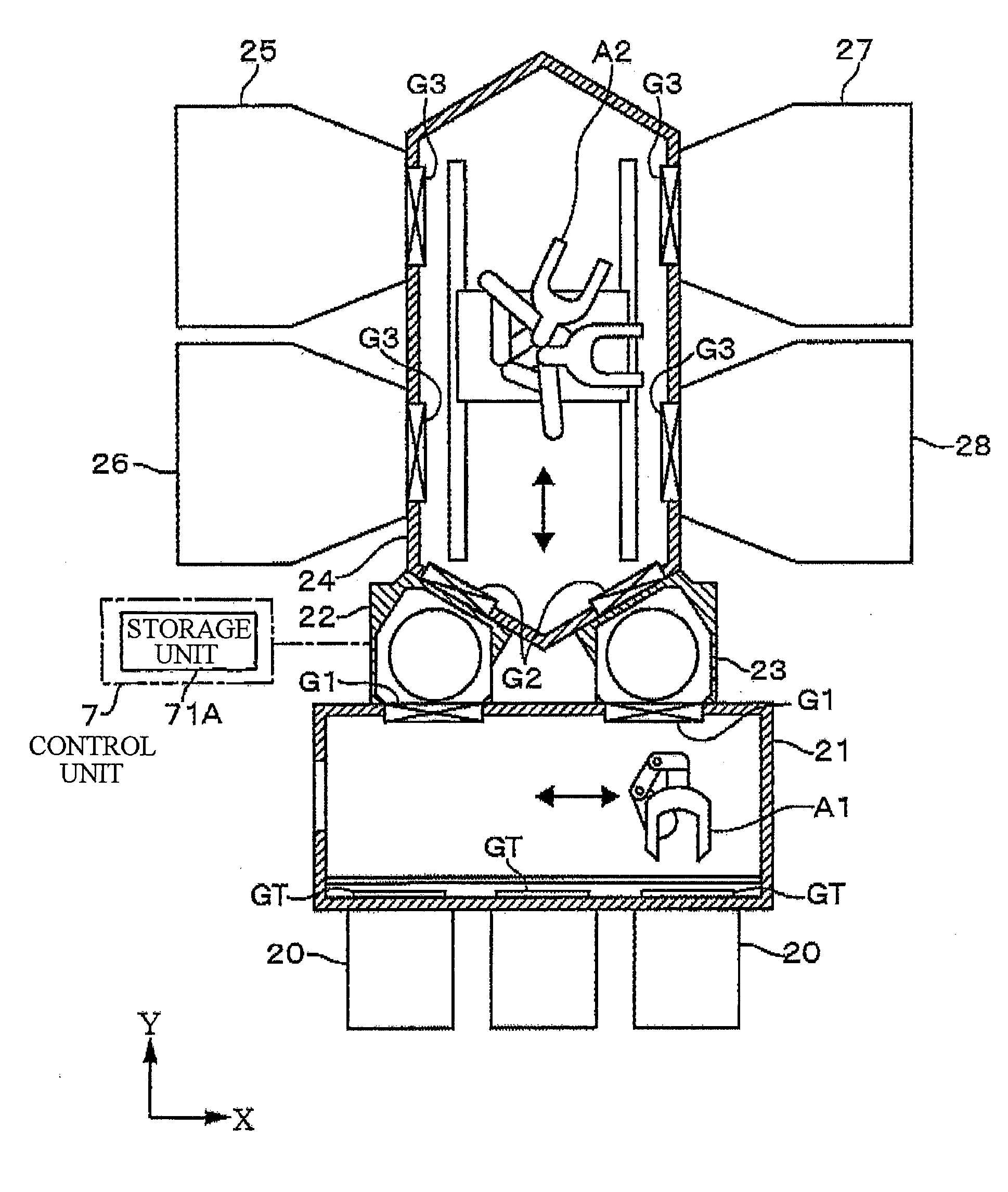
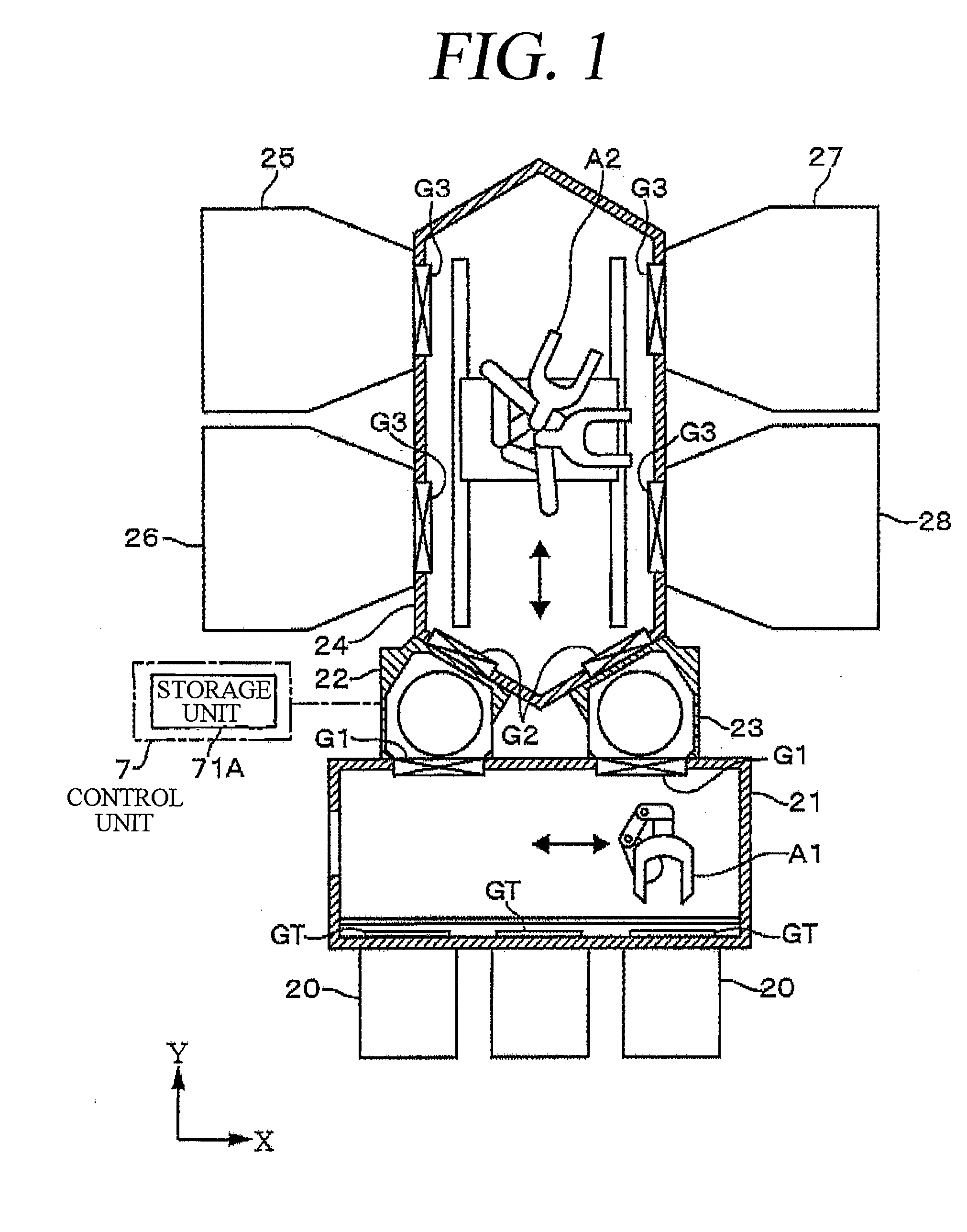
[0034]Hereinafter, an embodiment of the present invention will be described with reference to FIG. 1. In FIG. 1, a reference numeral 20 denotes a plurality of, for example, three airtight carriers, each for accommodating a number of wafers W therein. The carriers 20 are respectively connected to a wall portion of one side of a first transfer chamber 21 via doors GT to be arranged in X direction of the figure. Further, two preliminary vacuum chambers 22 and 23 are also connected to, for example, an opposite wall portion of the first transfer chamber 21 via respective gate valves G1 to be arranged in the X direction, the opposite wall portion being opposite to the wall portion where the carriers 20 are connected.

[0035]The first transfer chamber 21 is regulated to be under a normal pressure atmosphere. The normal pressure atmosphere may be an atmospheric atmosphere or a normal pressure atmosphere of a nonreactive gas. Further, a first transfer arm A1 is disposed in the first transfer c...


PUM


Abstract

A vacuum processing apparatus transfers a wafer between a first transfer arm and a second transfer arm via a rotary stage; acquires position data of a peripheral portion of the wafer by using a line sensor while rotating the rotary stage sustaining the wafer before a vacuum process thereon; calculates a center position and a direction of the wafer based on the position data; controls a rotation of the rotary stage to adjust the direction of the wafer based on the calculation result; and controls the second transfer arm such that the second transfer arm conveys the wafer to a wafer mounting member inside a vacuum processing chamber while allowing a center of the wafer to be aligned to a center of the mounting member based on the calculation result.

Description

FIELD OF THE INVENTION[0001]The present disclosure relates to a vacuum processing apparatus for performing a vacuum process on a semiconductor wafer in a vacuum processing chamber after transferring the semiconductor wafer into the vacuum processing chamber via a preliminary vacuum chamber and a vacuum transfer chamber under a normal pressure atmosphere; and also pertains to a vacuum processing method performed by using the vacuum processing apparatus and a storage medium for executing the method.BACKGROUND OF THE INVENTION[0002]A manufacturing process of a semiconductor device includes a process of performing a vacuum process such as an etching process, a film forming process, an ashing process, or the like on a wafer which is a semiconductor substrate. Known as an apparatus to be used to perform these vacuum processes is a multi-chamber type vacuum processing apparatus having a configuration which connects a plurality of vacuum processing chambers to a common transfer chamber unde...

Claims


Application Information

Patent Timeline
Patent Type & Authority Applications(United States)
IPC IPC(8): H01L21/677
CPCH01L21/68H01L21/67748
Inventor KONDOH, KEISUKE
Owner TOKYO ELECTRON LTD
Why Eureka
Try Eureka