
Method and system for wireless design subject to interference constraints

Inactive Publication Date: 2008-08-07
NTT DOCOMO INC
View PDF12 Cites 13 Cited by
  • Summary
  • Abstract
  • Description
  • Claims
  • Application Information

AI Technical Summary

Benefits of technology

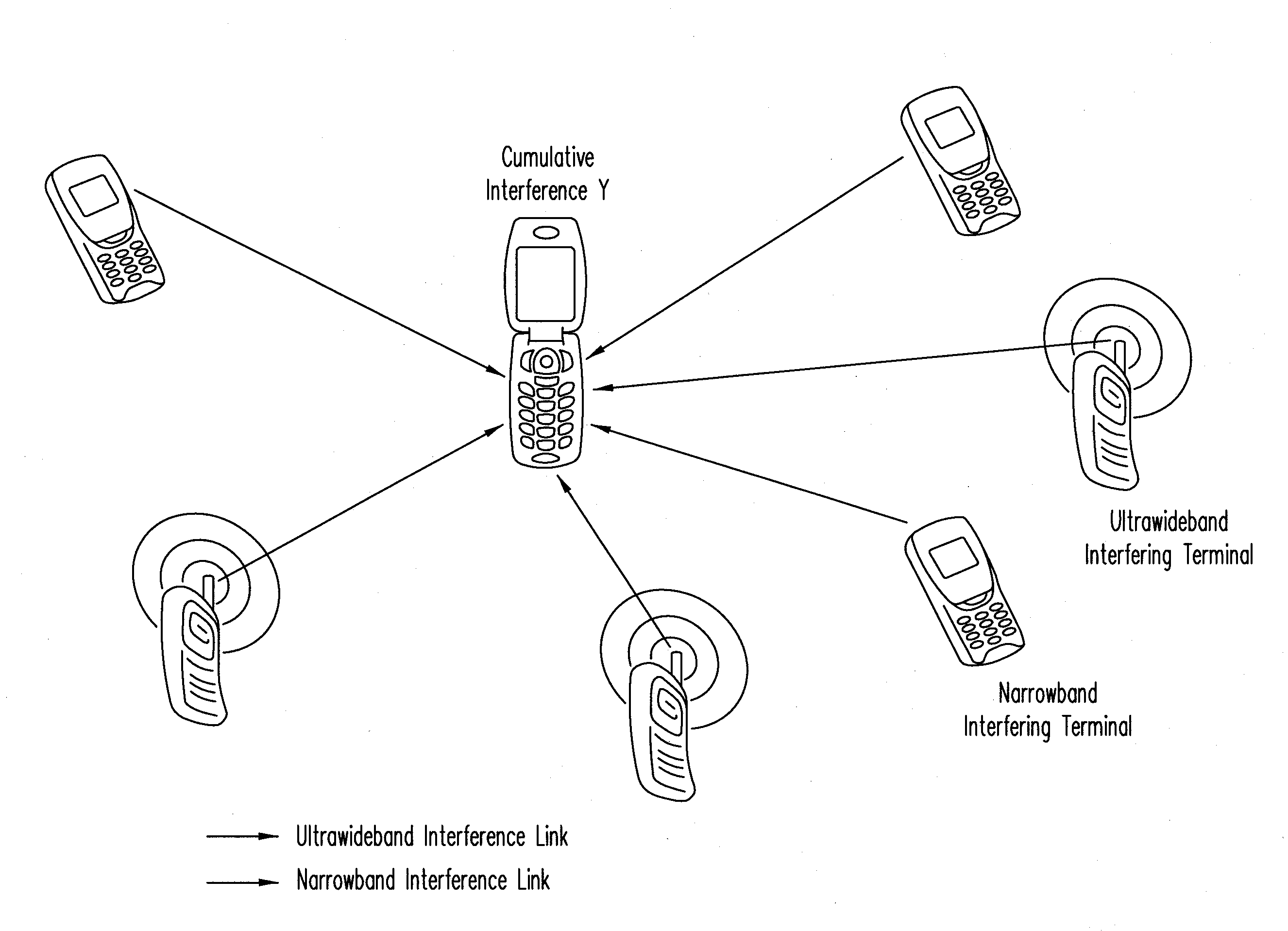
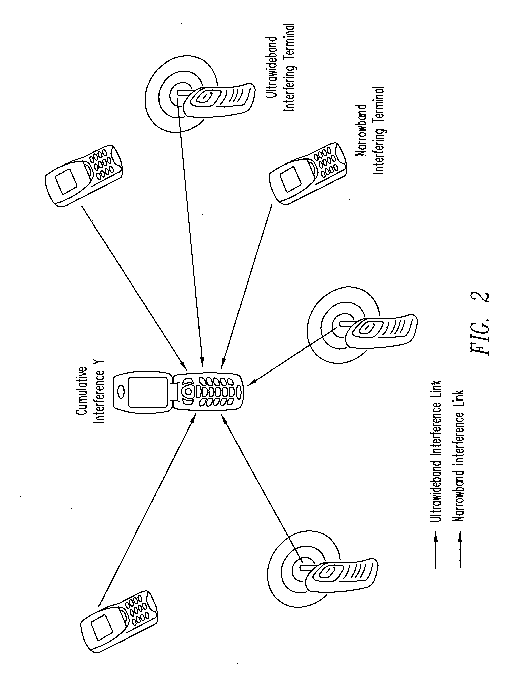
[0010]A wireless communication system experience interference from other wireless communication networks. A method for designing wireless communication systems subject to interference is provided based on a realistic interference model which accounts for the propagation effects introduced by the wireless environment (such as path loss, shadowing, and multipath fading), and the spatial scattering of transmitters (using a Poisson field). The method acc

Problems solved by technology

For example, U.S. Patent Application Publication 2005 / 0163042 A1, entitled “Wireless Ultra Wideband Network Having Interference Mitigation and Related Methods”, by R. D. Roberts, published on Jul. 28, 2005, discloses an ultra-wide band (UWB) system architecture with interference mitigation capabilities, but does not provide a framework for a heterogeneous network.
These methods do not account for random propagation effects (e.g., path loss, shadowing and multipath fading) and are restricted to non-coherent modulations.
Such synchronization restriction is typically impractical.
This approach presupposes a finite number of interferers, complicates the design procedure, and does not provide a useful tool for network design.
In general, the above methods of the prior art do not account for many parameters that are important to network design, such as signal-to-noise ratio (SNR), interference-to-noise ratio (INR), path loss exponent, spatial density of the interferers, and error probability.
A wireless communication system experience interference from other wireless communication networks.

Method used


Image

  • Method and system for wireless design subject to interference constraints
  • Method and system for wireless design subject to interference constraints
  • Method and system for wireless design subject to interference constraints

Examples


Embodiment Construction

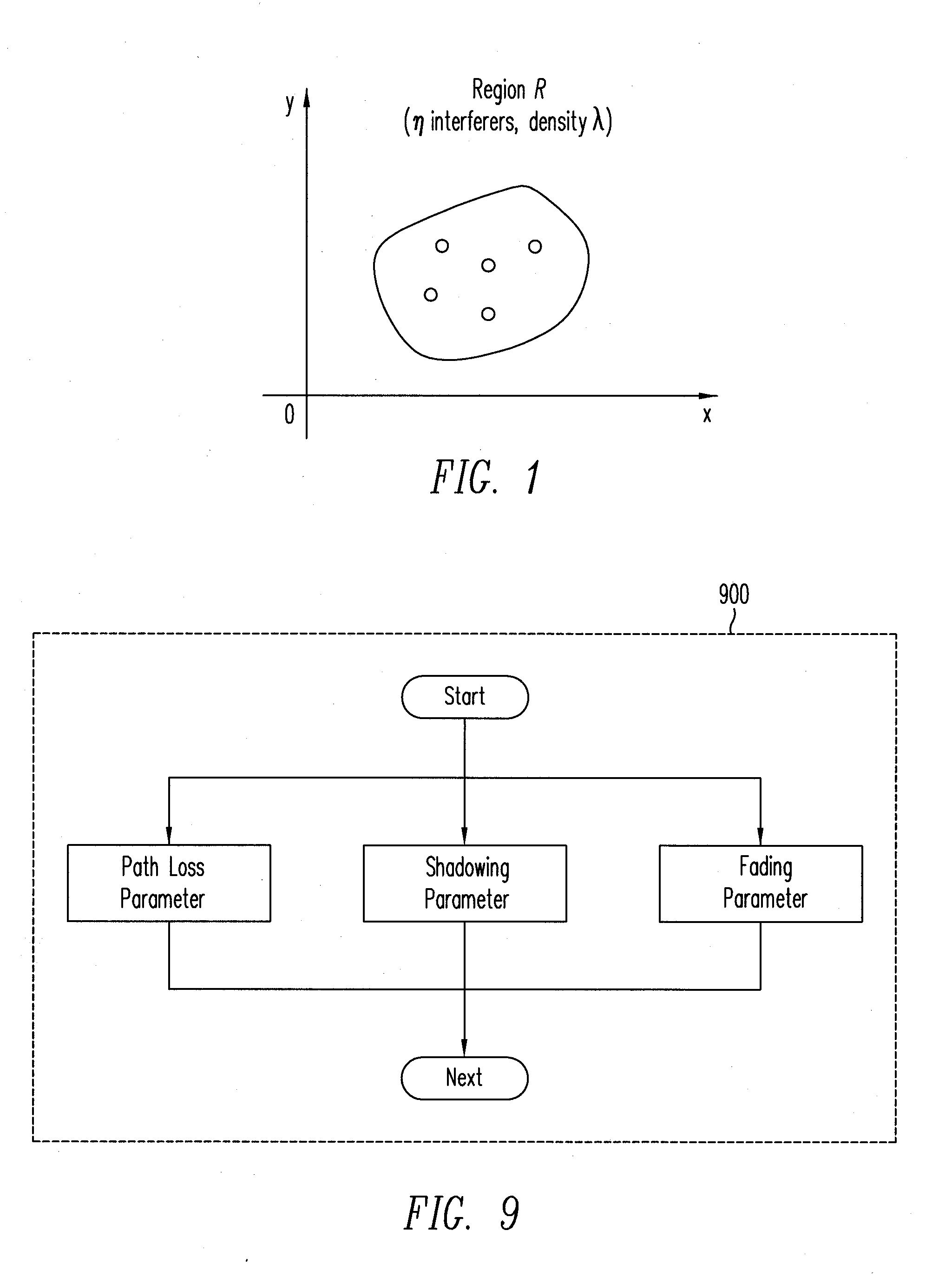
[0026]FIG. 1 illustrates a spatial distribution of transmitters in a network design framework, according to one embodiment of the present invention. As shown in FIG. 1, for example, the transmitters are distributed spatially according to a homogeneous Poisson point process in a 2-dimensional (2-D) infinite plane. Consequently, the probability of finding n interferers inside a given region R (not necessarily connected) depends only on the total area A of the region, and is given by:

P{ninR}=(λA)nn!-λA,(1)

[0027]where λ is a (constant) spatial density of interfering nodes, expressed in nodes per unit area. Under this model, the interfering nodes form a set of terminals that transmit within the frequency band of interest and during the time interval of interest (e.g., one symbol period). These interfering nodes therefore effectively contribute to the total interference. Regardless of the network topology (e.g., unicast, multicast, broadcast, etc.) or the multiple-access technique used (e...


PUM


Abstract

A wireless communication system experience interference from other wireless communication networks. A method for designing wireless communication systems subject to interference is proposed based on a realistic interference model which accounts for the propagation effects introduced by the wireless environment (such as path loss, shadowing, and multipath fading), and for the spatial scattering of transmitters (using a Poisson field). The method accounts for tradeoffs between network parameters, such as signal-to-noise ratio (SNR), interference-to-noise ratio (INR), path loss exponent, spatial density of the interferers, and error probability. Advantages of this method include: 1) a unified framework for designing a wireless system, subject to cumulative interference and noise, incorporating a wide range of performance metrics; and 2) a general application that covers a broad class of wireless communication systems and channel fading distributions.

Description

CROSS-REFERENCE TO RELATED APPLICATIONS[0001]The present application is related to and claims priority to U.S. provisional patent application Ser. No. 60 / 887,540, entitled “Method and System for Wireless Design Subject to Interference Constraints,” filed on Jan. 31, 2007. The U.S. provisional patent application is hereby incorporated by reference in its entirety.BACKGROUND OF THE INVENTION[0002]1. Field of the Invention[0003]The present invention relates to wireless communication. In particular, the present invention relates to design of a wireless communication system subject to interference constraints.[0004]2. Discussion of the Related Arts[0005]Various wireless network design methods to minimize interference from other networks and improve the reliability in wireless communication systems have been proposed. For example, U.S. Patent Application Publication 2005 / 0163042 A1, entitled “Wireless Ultra Wideband Network Having Interference Mitigation and Related Methods”, by R. D. Rob...

Claims


Application Information

Patent Timeline
IPC IPC(8): H04B15/00H04B7/00
CPCH04W16/22
Inventor CHONG, CHIA-CHINPINTO, PEDRO C.WIN, MOE Z.WATANABE, FUJIOINAMURA, HIROSHI
Owner NTT DOCOMO INC
Learn More