
Method for Manufacturing Laminated Board and Apparatuses Used on the Same

Inactive Publication Date: 2008-08-14
LEE YIMING
View PDF1 Cites 0 Cited by
  • Summary
  • Abstract
  • Description
  • Claims
  • Application Information

AI Technical Summary

Benefits of technology

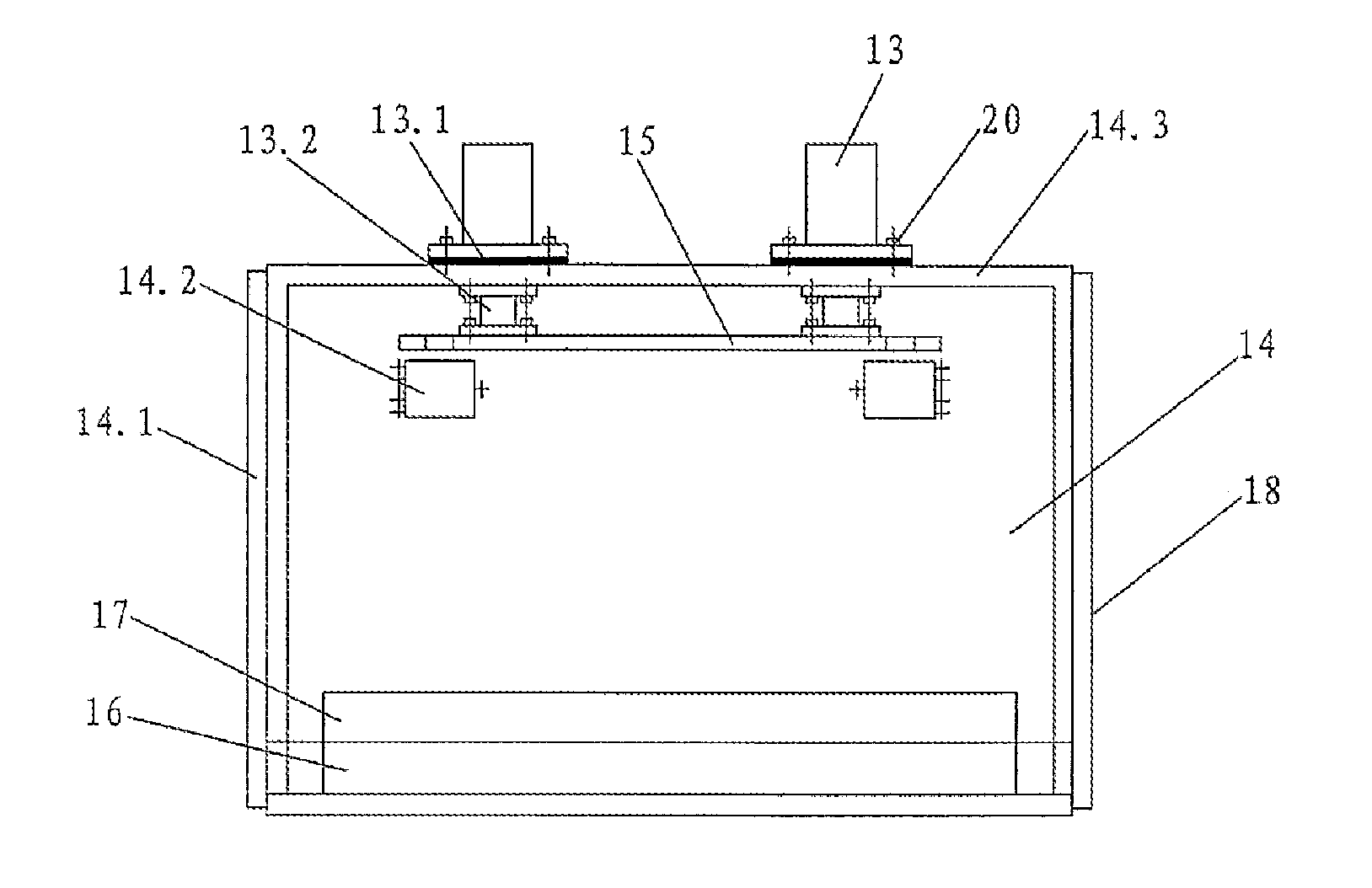
[0003]For overcoming the shortcomings exited in the conventional technology, the main object of the present invention is to provide a method for manufacturing laminated board and the apparatuses used on the same for reducing the equipment cost, enlarging the production scale, fully taking the advantage of the vacuum cabinet to carry out assembly line production, improving the production efficiency and reducing manufacturing cost.
[0018]Said step of putting the trailer carrier loaded with a set of stacked laminated boards at inside of the vacuum pressure device includes that after placing the trailer carrier loaded with a set of stacked laminated boards into the inside of the vacuum pressure device, by plugging the latches the combined base of the hydraulic actuating mechanism is connected to the guide pillars; then lift up the top board a bit via the connection by the hydraulic actuating mechanism so that the top board is apart from the top sheet of the laminated board more than 1 mm, 1 cm to 1 m in general, for avoiding the vacuum of the binder layer between the sheets of the laminated board affecting by the weight force coming from the top board.
[0026]Comparing with the conventional technology, above-described technology project has following advantages:
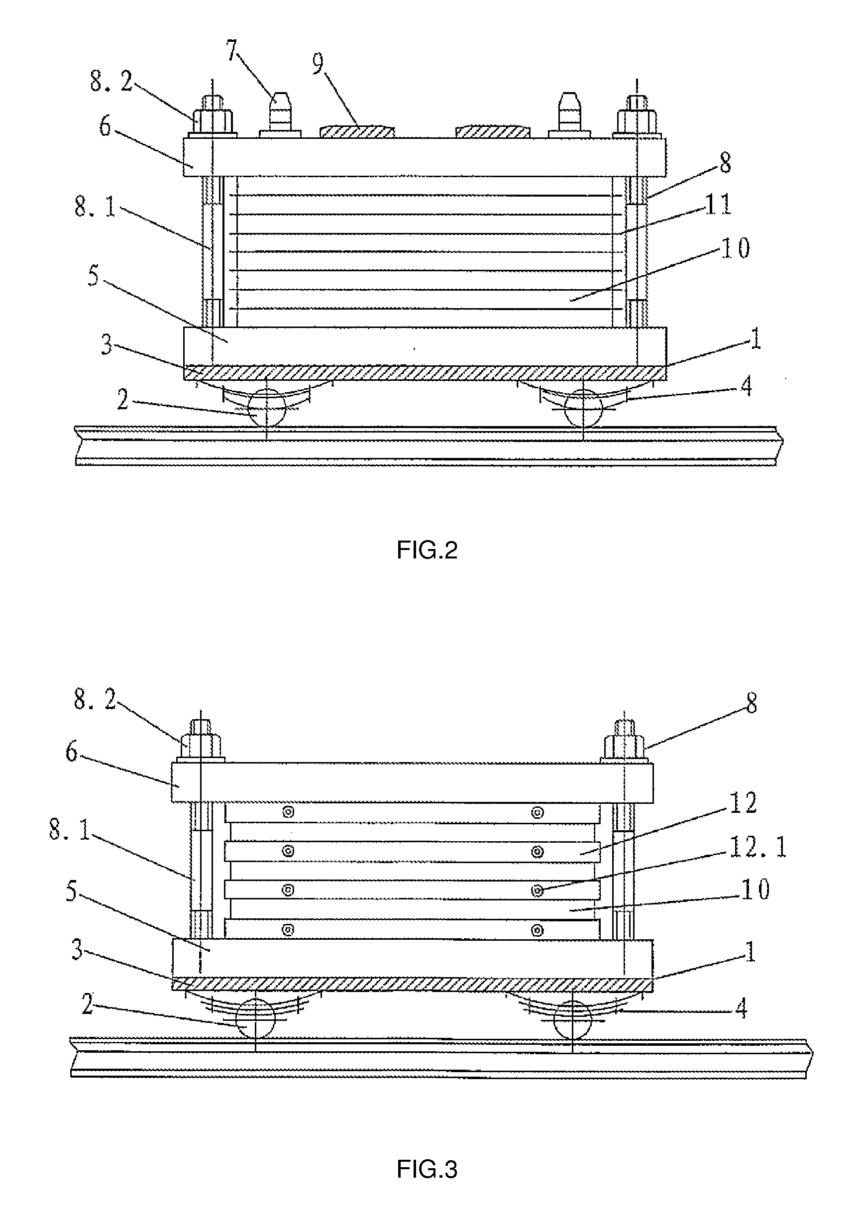
[0028]2. due to the vacuum pressure device of the present invention integrated the vacuum device and press into one body, so the vacuum pressure device has two functions simultaneously of vacuuming and pressing so that the vacuum pressure device is utilized fully, additionally due to the cooperation of the pressure block, the top board and the fasteners on the trailer carrier, the trailer carrier has not to be equipped with a press on, so a vacuum pressure device can be equipped with many trailer carriers, it not only reduces the equipment cost, but also enlarges the manufacturing scale to carry out flow-line production.

Problems solved by technology

Due to the carriages built on the both sides of the oil press, the stacking process will become inconvenient, and because the vacuum cabinet is used for vacuuming only and the oil press is used just for pressing, so only by pushing the oil press in or out the vacuum cabinet can the works be carried out, additionally the oil press is very heavy, so the operation is quite inconvenient as pushing in and out, and the operating efficiency is poor, additionally there is a big scale demand in the market, if there is only one oil press available, it signifies that the vacuum cabinet will be idle for 3˜4 hours in a cycle, so that this operating efficiency can not meet the requirement of the market, if increasing the number of the oil presses, the equipment investment will be increased, so how to decrease the manufacturing cost of the equipment, enlarge the production scale, fully take the advantage of the vacuum cabinet to carry out assembly line production, improve production efficiency and reduce cost are the issues expected to be solved.

Method used


Image

  • Method for Manufacturing Laminated Board and Apparatuses Used on the Same
  • Method for Manufacturing Laminated Board and Apparatuses Used on the Same
  • Method for Manufacturing Laminated Board and Apparatuses Used on the Same

Examples


Embodiment Construction

[0040]Referring to the attached drawings, following embodiments will be described minutely, within the similar mechanical structures in the different drawings will use the same notation in their own drawings as illustrating in the description. It should be stressed that following detailed description is just only demonstration that should not be understood as a strict constraint to the claimed range of the claim of the present invention.

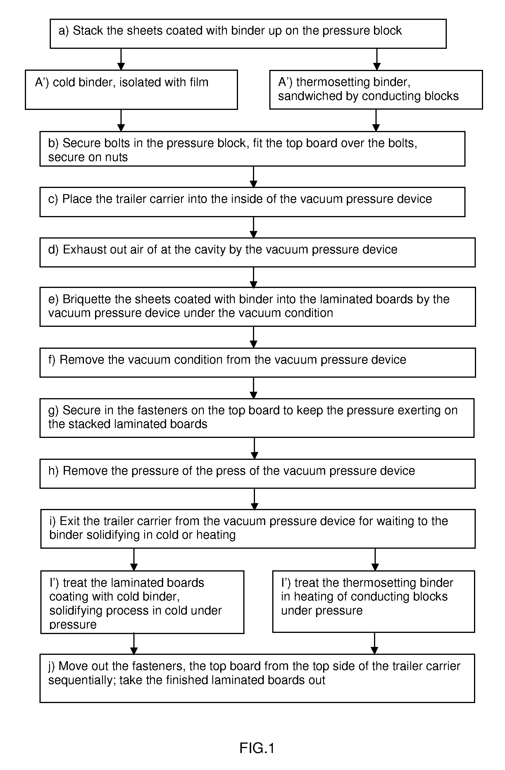
[0041]FIG. 1 is showing the steps of the method provided by the present invention:[0042]a) stack the sheets coated with binder of the laminated board up on the pressure block of the trailer carrier;[0043]b) secure in the blots of the fasteners on the pressure block, fit the top board over the bolts, secure on nuts;[0044]c) place the trailer carrier stocked with the stacked laminated boards into the inside of the vacuum pressure device;[0045]d) exhaust out air of at the cavity by the vacuum pressure device;[0046]e) briquette the sheets coated with bin...


PUM

PropertyMeasurementUnit
Pressureaaaaaaaaaa
Efficiencyaaaaaaaaaa

Abstract

The present invention provides a method for manufacturing laminated board and apparatuses used on the same involving the laminated board flow-line production field, in which the method is to stack the sheets coated with binder of the laminated board up on the pressure block of the trailer carrier placed into the inside of the vacuum pressure device, to briquette the sheets coated with binder into the laminated boards by the vacuum pressure device under the vacuum condition, to secure in the fasteners on the top board to keep the pressure exerting on the stacked laminated boards after exiting the trailer carrier from the vacuum pressure device for waiting to the binder solidifying in cold or heating; to secure out the fasteners, the top board from the top side of the trailer carrier sequentially, finally take the finished laminated boards out to empty the trailer carrier for the next circulation; the apparatuses used for manufacturing the laminated board includes a vacuum pressure device for taking to briquette the laminated boards and trailer carriers comprising a pressure block, a top board, and fasteners, and conducting blocks used for heating the thermosetting binder to solidify. The present invention not only can reduce the equipment cost, but also enlarge the production scale and improve production efficiency to carry out flow-line production to meet the requirement of the market.

Description

BACKGROUND OF THE INVENTION[0001]The present invention relates to a laminated board, and more especially to a method for manufacturing laminated board and the apparatuses used on the same.[0002]In accordance with the conventional wooden laminated board, artificial stone laminated board, stone laminated board, fiberglass reinforced plastics and so on, they are widely used in decorating inner and outer of room, such as kitchens, bathrooms or wine bars and so on, among of them the description of a Chinese patent No.: 200310116851.4 reveals a method for manufacturing artificial stone laminated board, in which the stoke preparation is taken up on the worktable of the hydraulic press, such like stacking up the sheets of the laminated board on the worktable of the oil press, and pushing the oil press loaded with the stacked sheets of the laminated board into the inside of the vacuum cabinet along the track-way for vacuuming, and after releasing the oil press from the vacuum state into norm...

Claims


Application Information

Patent Timeline
IPC IPC(8): B29C65/02
CPCB32B37/0046B32B37/1018B32B2607/00B32B2479/00B32B37/12
Inventor LEE, YIMING
Owner LEE YIMING
Learn More