Cargo Handling Apparatus of Cargo Handling Industrial Vehicle

a technology of cargo handling and industrial vehicles, applied in the direction of electric propulsion mounting, electric devices, propulsion by batteries/cells, etc., can solve the problems of inefficient driving of forks, achieve high load, ensure responsiveness, and improve energy efficiency

Inactive Publication Date: 2008-08-14
TOYOTA IND CORP
View PDF1 Cites 20 Cited by
  • Summary
  • Abstract
  • Description
  • Claims
  • Application Information

AI Technical Summary

Benefits of technology

[0015]According to the present invention, when the cargo handling load is smaller than the predetermined value, the transmission of the power between the engine and the generator-motor is disconnected by the clutch, the cargo handling means is driven by the generator-motor in the motor mode, and the engine is idled or stopped, thus making it possible to enhance energy efficiency. Then, when the cargo handling load is increased to the predetermined value or more, the control to increase the output of the generator-motor is first performed to thereby ensure the responsiveness. Further, when the increase of the cargo handling load is detected, the number of revolution of the engine is increased, and when the number of revolution of the engine is made equal to the number of revolution of the generator-motor, the transmission of the power between the engine and the generator-motor is connected by the clutch. Accordingly, the large load is prevented from being applied to the generator-motor from the engine side. Further, the clutch is set to the connected state when the number of revolution of the engine and the number of revolution of the generator-motor coincide with each other. Accordingly, the load on the clutch can also be reduced.

Problems solved by technology

Hence, when such a cargo handling load is small, it is inefficient to drive the fork by a large output of the engine, and it is therefore preferable to drive the fork only by the generator-motor while stopping the engine or setting the engine in an idle state.

Method used


Image

  • Cargo Handling Apparatus of Cargo Handling Industrial Vehicle
  • Cargo Handling Apparatus of Cargo Handling Industrial Vehicle
  • Cargo Handling Apparatus of Cargo Handling Industrial Vehicle

Examples


first embodiment

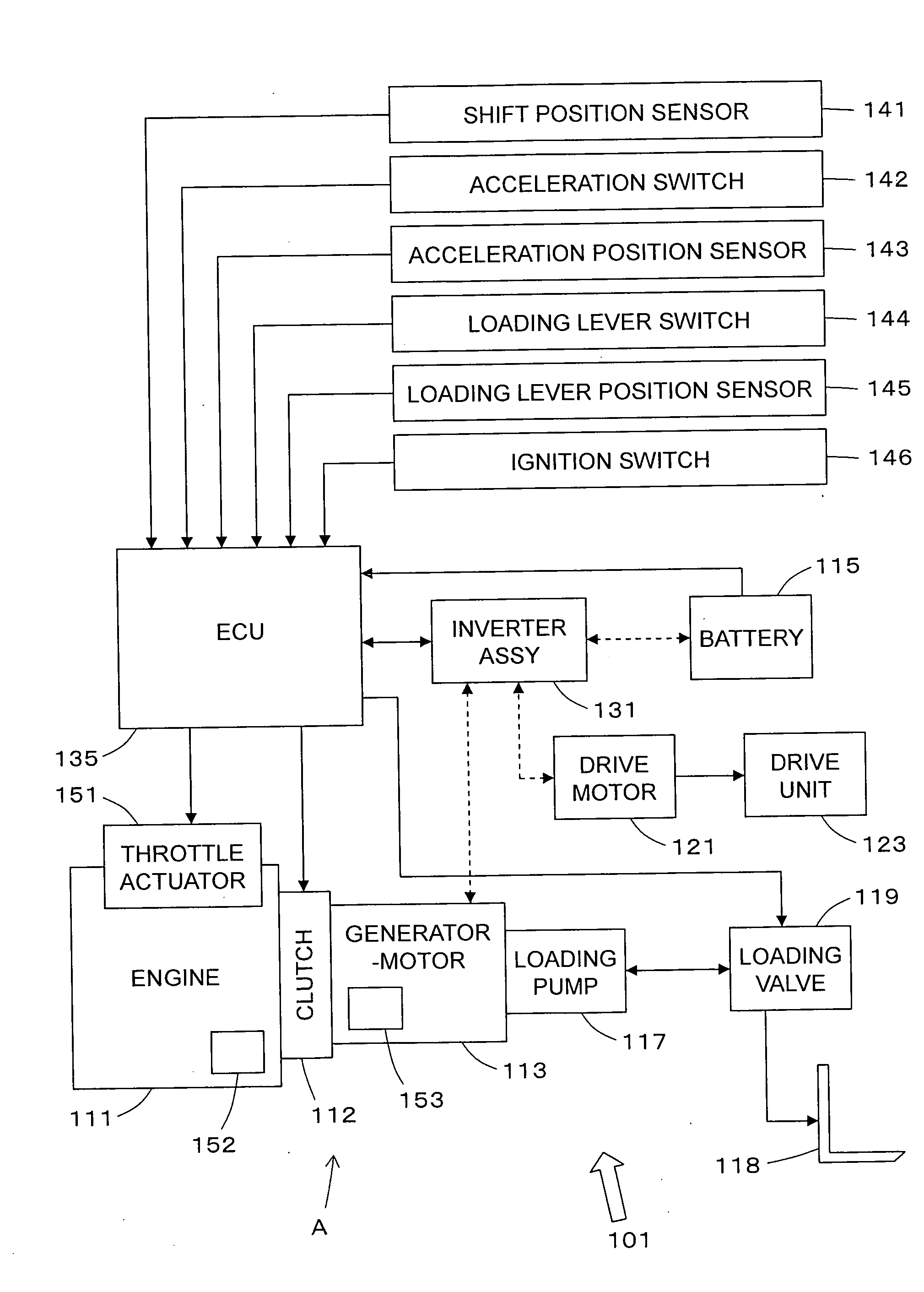
[0023]A cargo handling apparatus A of a forklift 101 according to a first embodiment of the present invention, which is shown in FIG. 1, is mainly composed of an engine 111, a generator-motor 113, a battery (electric storage means) 115, a loading pump 117, a loading valve 119, a fork 118, a drive motor 121, a drive unit 123, an inverter assembly 131, and an ECU (controller) 135. Cargo handling means is mainly composed of the loading pump 117, the fork 118, and the loading valve 119.

[0024]The engine 111 is driven through a rotation control signal given to a throttle actuator 151 from the ECU 135 to be described later, and a drive shaft (not shown) thereof is coaxially coupled to a drive shaft (not shown) of the generator-motor 113 through a clutch 112 for disconnecting / connecting the power.

[0025]The generator-motor 113 is driven by the engine 111 to generate power, and is appropriately switchable between a generator mode of storing the power in the battery 115 and a motor mode in whi...

second embodiment

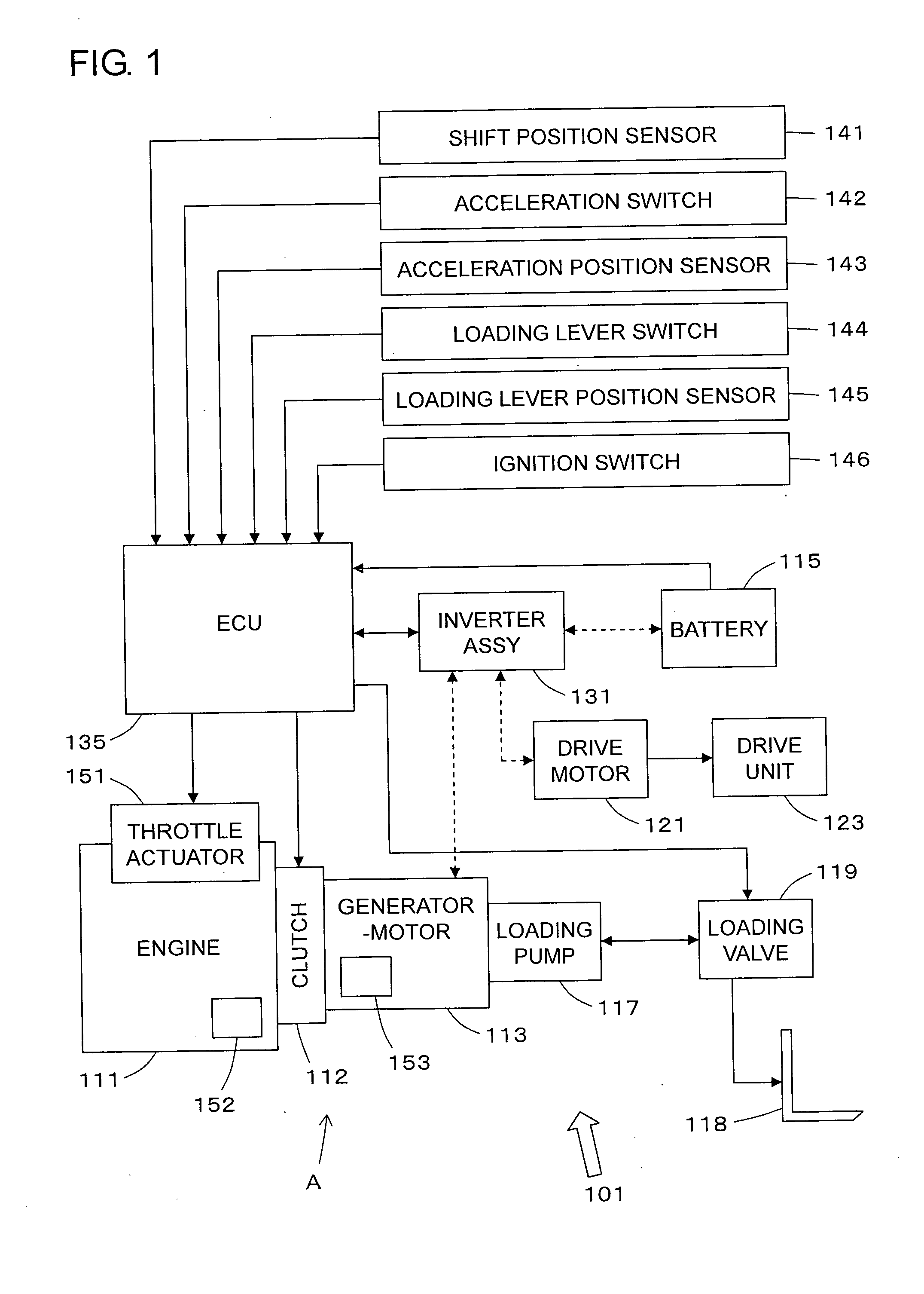
[0048]FIG. 2 is a block diagram showing a construction of a forklift of a second embodiment. In comparison with the above-described first embodiment, this second embodiment is different therefrom in that a CVT (continuously variable transmission) 114 is interposed between the generator-motor 113 and the engine 111. It is possible to control a transmission gear ratio of this CVT 114 by a control signal from the ECU 135.

[0049]With this construction, when, for example, the opening of the loading lever, which is detected by the loading lever position sensor 145, is increased during the cargo handling work in the above-described third mode (where the clutch 112 is in the disconnection state, and the engine 111 is in the idle state or the stopped state) to cause the increase of the cargo handling load, and the degree of increase of the cargo handling load is the predetermined value or more, a control is made to increase the output of the generator-motor 113 in the motor mode, and to immed...

third embodiment

[0055]A forklift of a third embodiment of the present invention is shown in FIG. 3. This forklift 101 is constructed such that a one-way clutch 112′ is provided between the generator-motor 113 and the engine 111 in place of the clutch 112 in the construction of FIG. 1.

[0056]With this construction, when the generator-motor 113 is driven in the above-described third mode while the engine 111 is set to the idle state or the stopped state, since the number of revolution of the engine 111 is smaller than the number of revolution of the generator-motor 113, the one-way clutch 112′ is automatically set to the disconnection state. Hence, the large load (engine braking) is prevented from being applied to the generator-motor 113 in case of driving the loading pump 117 by driving the generator-motor 113 in this third mode.

[0057]Then, when, for example, the opening of the loading lever, which is detected by the loading lever position sensor 145, is increased during the cargo handling work in th...


PUM


Abstract

Provided are an engine 111, a generator-motor 113, a clutch 112 connecting/disconnecting power therebetween, a battery 115, and a loading pump 117 for driving a fork 118. The generator-motor 113 is set either in a generator mode or in a motor mode. When a cargo handling load (detected by a loading lever position sensor 145 and the like) is smaller than a predetermined value, the clutch 112 is set to a disconnection state, the engine 111 is stopped or idled, and the loading pump 117 is driven by the generator-motor 113 in the motor mode. When the load is increased to the predetermined value or more during cargo handling work in a state where the clutch 112 is released, an increase of the number of revolution of the engine is started while an output of the generator-motor 113 is being increased. When the number of revolution of the engine 111 is made equal to the number of revolution of the generator-motor 113, the clutch 112 is set to a connected state, and the loading pump 117 is driven by the engine 111.

Description

TECHNICAL FIELD[0001]The present invention relates to a so-called hybrid handling apparatus provided for a cargo handling industrial vehicle.BACKGROUND ART[0002]As this type of cargo handling apparatus, for example, there is a cargo handling apparatus of a forklift, which is disclosed in undermentioned Document 1. This cargo handling apparatus includes an engine, a generator-motor, a battery, and a fork. Then, the generator-motor is driven either in a generator mode in which the generator-motor is driven by the engine to generate electric power or in a motor mode in which the generator-motor is driven as a motor by receiving electric drive power from the battery. The cargo handling apparatus is made switchable between a first drive mode in which the cargo handling apparatus is driven by the engine to perform cargo handling work and a second drive mode in which the cargo handling apparatus is driven by the engine and the generator-motor in the motor mode to perform the cargo handling...

Claims


Application Information

Patent Timeline
Patent Type & Authority Applications(United States)
IPC IPC(8): B66F9/24B60W20/00B60K6/46B60K6/543B60L50/16B60W10/02B60W10/06B60W10/08B66F9/20F16H59/14F16H59/42F16H61/02F16H61/66
CPCB60K6/46B60L1/003B60L11/123B60L2200/42B60L2220/14Y10S903/906B60Y2200/15B66F9/20Y02T10/6217Y02T10/7005Y02T10/7077B60W10/02B60L50/61Y02T10/62Y02T10/70Y02P90/60B66F9/24Y02T10/7072
Inventor KATO, NORIHIKOSUGAI, MASARU
Owner TOYOTA IND CORP
Why Eureka
Try Eureka