
Adaptive output current control for switching circuits

a switching circuit and output current technology, applied in the direction of ac-dc conversion, electric variable regulation, instruments, etc., can solve the problems of affecting the control of output curren

Active Publication Date: 2008-08-14
ANALOG DEVICES INT UNLTD
View PDF9 Cites 77 Cited by
  • Summary
  • Abstract
  • Description
  • Claims
  • Application Information

AI Technical Summary

Benefits of technology

[0008]The output current value may be determined so as to reduce variation of the output current with a change in the input voltage and the output voltage.
[0010]In accordance with another aspect of the disclosure, a system is provided for controlling an output current of switching circuitry including an input circuit for receiving an input voltage and an input current, and an output circuit for producing an output voltage. The output circuit is electrically isolated from the input circuit. The system comprises a switching control circuit for controlling a switching element in the input circuit so as to control the output current in the output circuit. The switching control circuit is configured for determining a value of the output current based on the input voltage, the input current, and a reflected output voltage obtained at the input circuit, and for controlling the switching element to reduce variation of the output current with change in the input voltage and the output voltage.
[0020]In accordance with an embodiment of the disclosure, the switching control circuit may adjust a peak level of switch current in the switching element to produce the output current at the calculated level.

Problems solved by technology

In addition, switching circuits may be subject to load uncertainty.
As the output current of the LED driver depends on the input voltage, variations in the input voltage level create substantial problems for accurate output current control.
However, the isolating arrangement also makes it more difficult to control the switching regulator since the control information should be relayed through the isolating barrier between the input and output sides of the regulator.
Moreover, an opto-coupler creates a propagation delay in a feedback loop of a LED driver reducing system dynamics and accuracy.

Method used


Image

  • Adaptive output current control for switching circuits
  • Adaptive output current control for switching circuits
  • Adaptive output current control for switching circuits

Examples


Embodiment Construction

[0041]The present disclosure will be made using the example of a system for controlling output current of a flyback switching regulator for a LED driver. It will become apparent, however, that the concept of the disclosure is applicable to any switching circuit that produces controllable output current in response to input voltage.

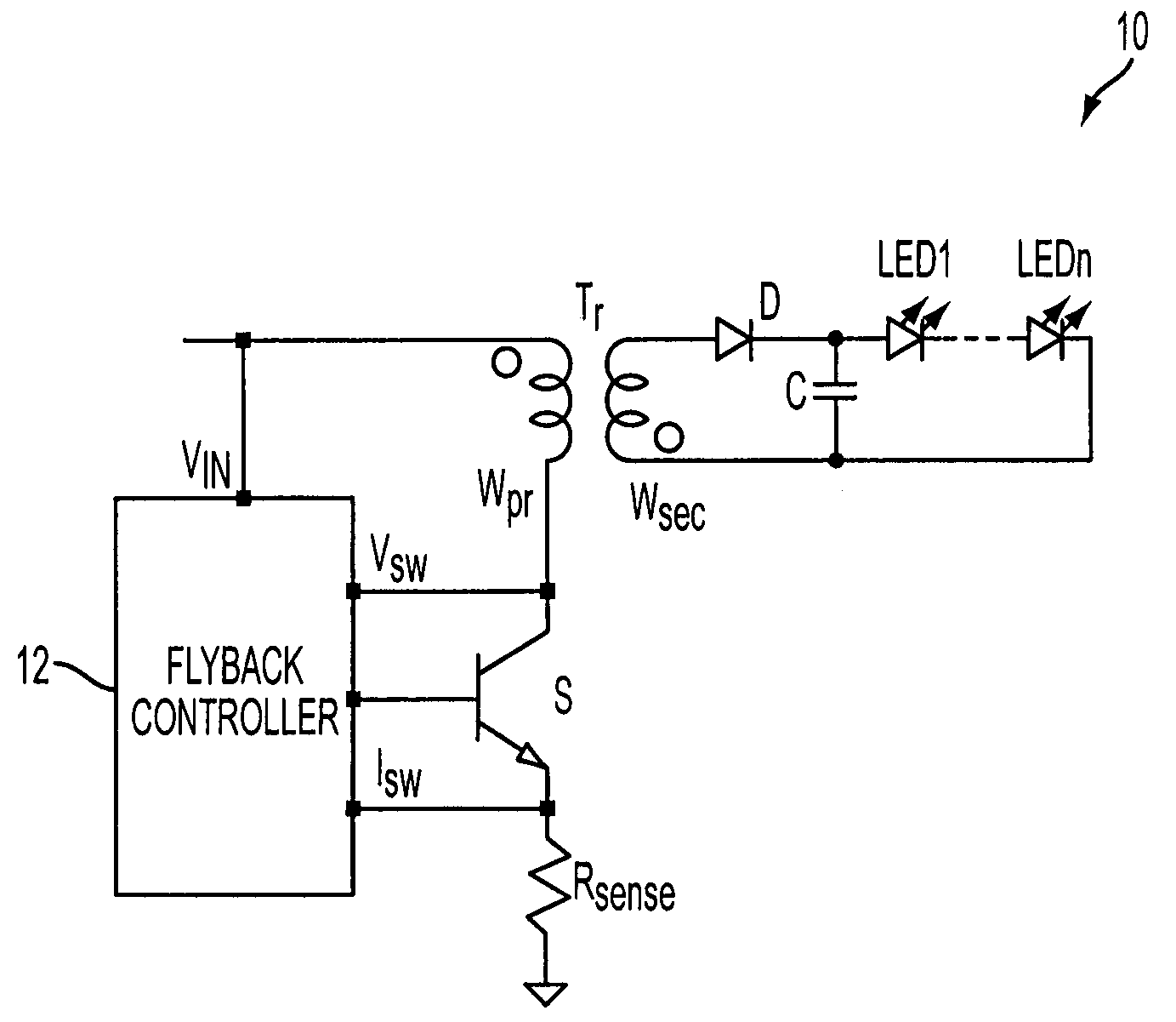
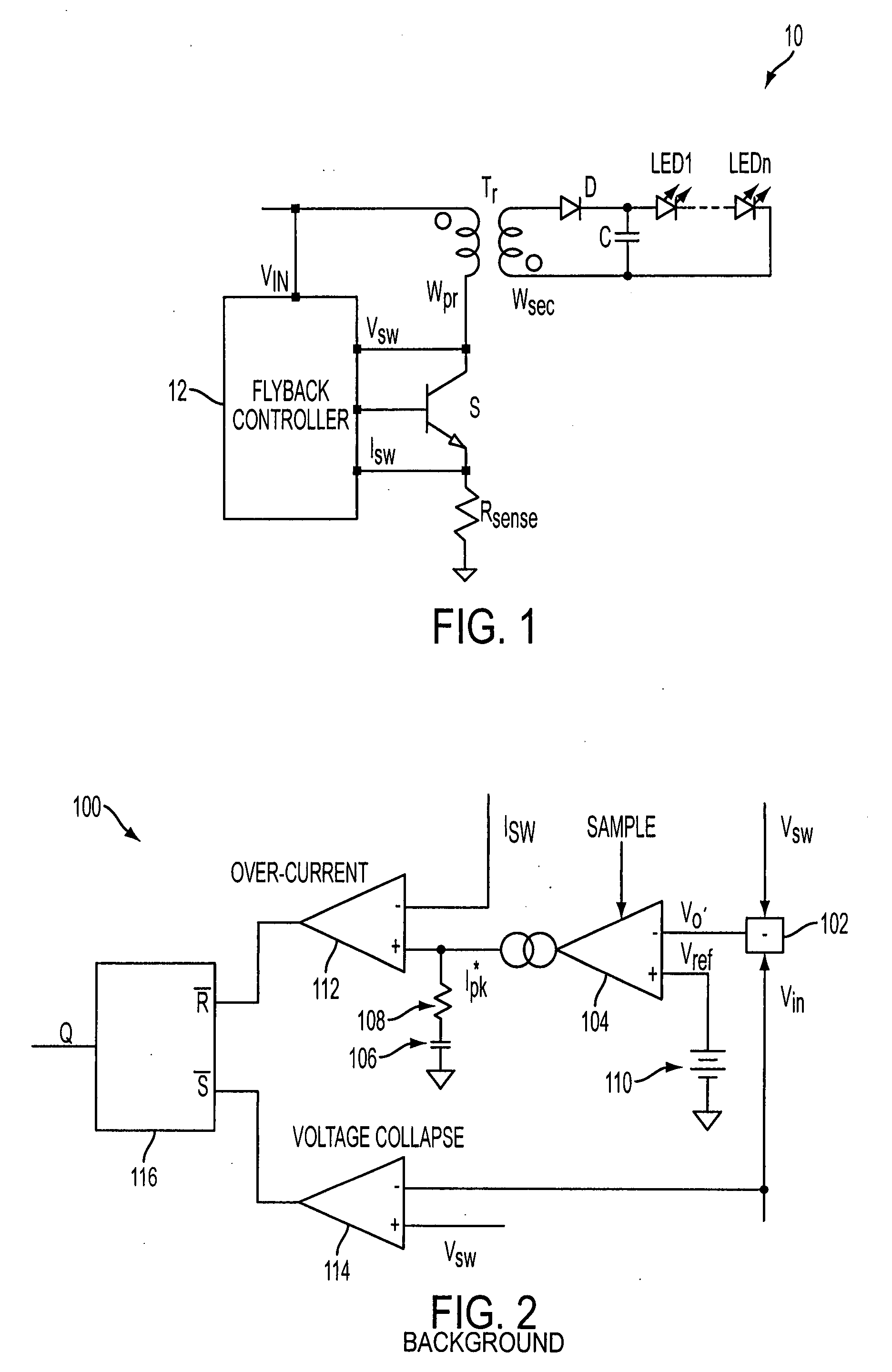
[0042]FIG. 1 illustrates an exemplary isolated flyback switching regulator 10 for a LED driver. The regulator 10 has a switching element S, a transformer Tr with primary and secondary windings wpr and wsec, and a controller 12 that controls switching of the switching element S. A sense resistor Rsense is coupled to the switching element S to monitor switch current Isw flowing through the switching element S. A capacitor C and a diode D are coupled to the secondary winding wsec, together with LEDs 1 to n, driven by the LED driver. The flyback switching regular 10 may convert an input DC voltage Vin into one or more output DC voltages with very high power co...


PUM


Abstract

System and methodology for controlling output current of switching circuitry having an input circuit and an output circuit electrically isolated from each other. A value of the output current may be determined based on input voltage, input current and reflected output voltage representing the voltage in the input circuit which corresponds to the output voltage. A switching element in the input circuit is controlled to produce the determined value of output current.

Description

TECHNICAL FIELD[0001]The subject matter of this disclosure relates to power supply circuits, and more particularly to circuitry and methodology for controlling output current in a switching regulator. The disclosure has particular applicability but is not limited to flyback converters.BACKGROUND[0002]Some switching circuits, such as switching regulators for light emitting device (LED) drivers, need to accept power from a variety of voltage sources that may provide a wide range of input voltages—from low voltages produced by DC sources to high voltages supplied from rectified AC lines. In addition, switching circuits may be subject to load uncertainty. For example, LEDs inherently have highly variable I-V characteristics. The variable number of LEDs that may be driven by a LED driver exaggerates the load uncertainty.[0003]Since the light emission of a LED is directly related to current flowing through the LED, the output current of a LED driver should be accurately controlled. As the...

Claims


Application Information

Patent Timeline
IPC IPC(8): H02M3/335
CPCH02M3/335
Inventor ZHOU, XIGENNG, DAVID ROYPIETKIEWICZ, STEVEN M.DOBKIN, ROBERT C.
Owner ANALOG DEVICES INT UNLTD
Learn More