System and Method for Physical-Layer Testing of High-Speed Serial Links in their Mission Environments

a technology of serial link and physical layer, applied in the field of physical layer testing of high-speed serial link in their mission environment, can solve the problems of affecting the deployment of such instruments, affecting the effectiveness of conventional physical layer test instruments, and requiring costly bench instruments

Inactive Publication Date: 2008-08-14
DFT MICROSYST
View PDF68 Cites 70 Cited by
  • Summary
  • Abstract
  • Description
  • Claims
  • Application Information

AI Technical Summary

Benefits of technology

[0006]One implementation of the present invention is a system for testing a high-speed serial link. The system includes: a physical-layer tester configured to be inserted into a high-speed serial link between a mission-environment transmitter and a mission-environment receiver, the physical-layer tester comprising: a tester receiver for receiving high-speed serial data from the mission-environment transmitter; a tester transmitter for transmitting the high-speed serial data to the mission-environment receiver; a data path extending between the tester receiver and the tester transmitter so as to carry the high-speed serial data from the tester receiver to the tester transmitter without loss; and a measurement path in communication with the tester receiver for receiving the high-speed serial data, the measurement path including measurement circuitry for measuring characteristics of the high-speed serial data.
[0008]Still another implementation of the present invention is a method of testing a high-speed serial link between a mission-environment transmitter and a mission-environment receiver. The method includes: providing a physical-layer tester that includes: a high-speed data input for receiving high-speed serial data output by a mission-environment transmitter; a high-speed data output for providing the high-speed serial data to a mission-environment receiver; a data path extending between the high-speed data input and the high-speed data output for carrying the high-speed serial data from the high-speed data input to the high-speed data output without loss; and a measurement path, in communication with the high-speed data input, for use in determining characteristics of the high-speed serial data; placing the high-speed data input into communication with a first device having a mission-environment transmitter; placing the high-speed data output into communication with a second device having a mission-environment receiver corresponding to the mission-environment transmitter; and conducting testing of the high-speed serial link between the mission-environment transmitter and the mission-environment receiver.

Problems solved by technology

Because of the complexity (non-determinism) of higher-level layers in a serial bus, conventional physical-layer test instruments rapidly become ineffective once a complete board or a system needs to be debugged and characterized.
For example, most PHY instruments require repetitive, deterministic data patterns to operate correctly, whereas live traffic is neither repetitive nor deterministic.
Other limitations hinder the deployment of such instruments in the test of complete links (multiple lanes) or systems.
To name a few limitations, the bench instruments needed are costly, they often do not have a large enough number of test channels, they often require the device under test to operate in artificial test modes (using deterministic stimulus), and they do not measure what an actual receiver on a board will “see.” Most importantly, present-day test instruments invariably require secondary interconnection paths through cables or similar connection mechanisms for the high-speed signals being measured.

Method used


Image

  • System and Method for Physical-Layer Testing of High-Speed Serial Links in their Mission Environments
  • System and Method for Physical-Layer Testing of High-Speed Serial Links in their Mission Environments
  • System and Method for Physical-Layer Testing of High-Speed Serial Links in their Mission Environments

Examples


Embodiment Construction

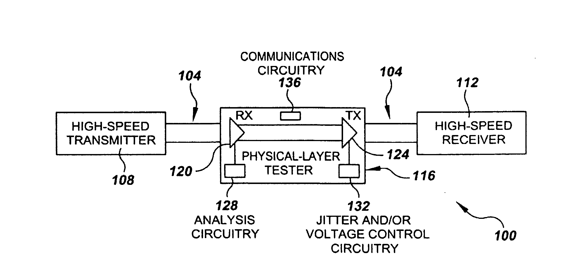
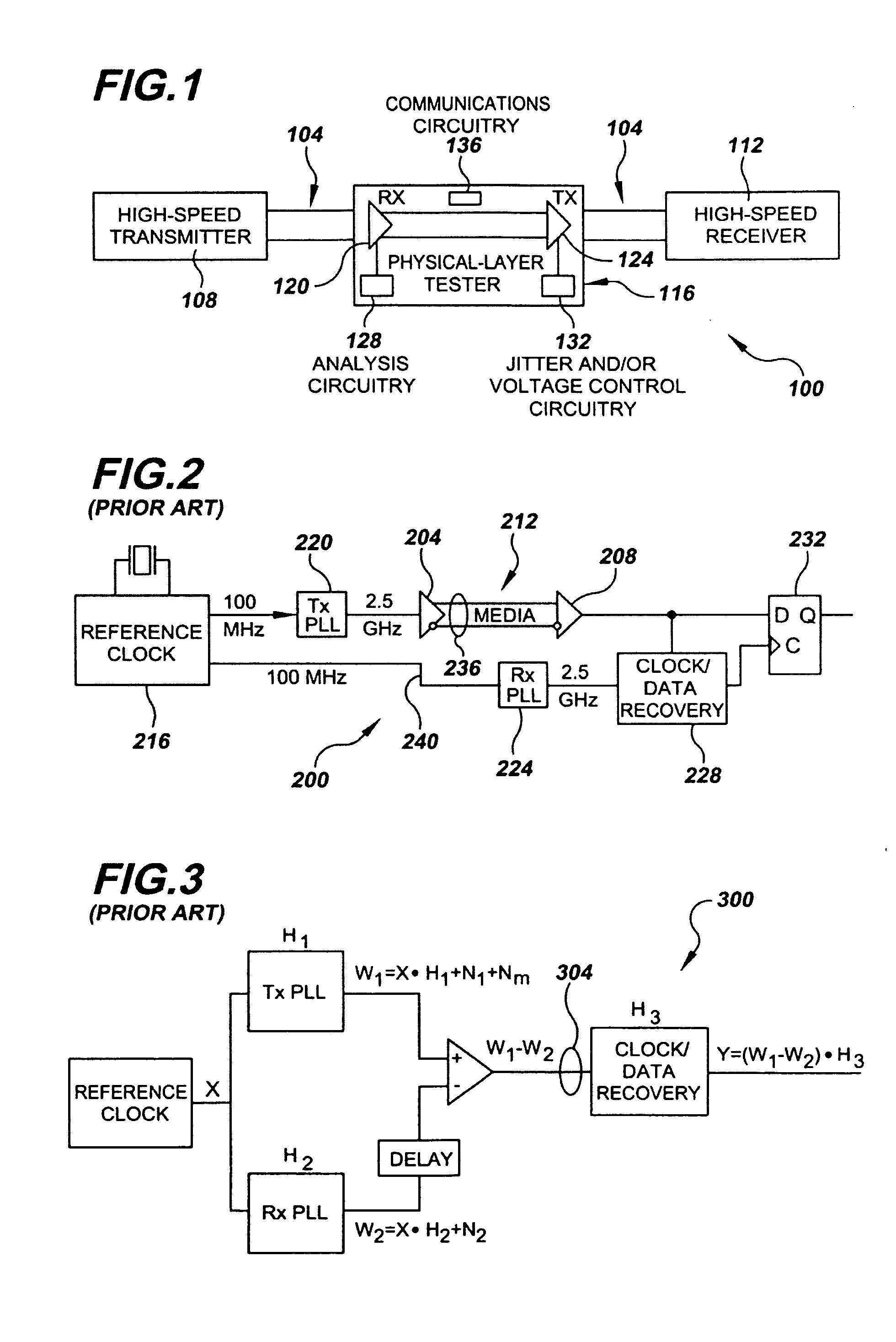
[0027]Referring now to the drawings, FIG. 1 illustrates an exemplary test setup 100 of the present invention. In this example, test setup 100 includes a high-speed serial data link 104 connecting a transmitter 108 (which may be part of a transceiver) and a corresponding high-speed receiver 112 (which, too, may be part of a transceiver) that is the intended mission-environment recipient of data transmitted by the transmitter. For the purpose of testing the physical layer of high-speed link 104, test setup 100 also includes a physical-layer tester 116 interposed in the high-speed link between transmitter 108 and receiver 112. As will be described below in detail, a primary purpose of test physical-layer tester 116 is to analyze the physical-layer of high-speed serial interfaces, such as high-speed serial link 104, as they operate within their mission environments.

[0028]By “mission environment,” and like terms, it is meant that the components (not shown), for example, motherboard and p...


PUM


Abstract

A physical-layer tester for testing a high-speed serial link between a mission-environment transmitter and a mission-environment receiver. The tester includes a data path and a measurement path. The data path allows a data signal transmitted from the mission-environment transmitter to be passed through the tester to the mission-environment receiver. The measurement path includes circuitry for use in analyzing characteristics of the high-speed serial data traffic on the high-speed serial link. The tester is placed in the high-speed serial link and allows the link to be tested while live, mission-environment data is present on the link. Methods for implementing in-link testing are also disclosed.

Description

RELATED APPLICATION DATA[0001]This application claims the benefit of priority of U.S. Provisional Patent Application Ser. No. 60 / 889,085, filed Feb. 9, 2007, and titled “Physical-Layer Testing Of Live In-System High-Speed Serial Links,” which is incorporated by reference herein in its entirety.FIELD OF THE INVENTION[0002]The present invention generally relates to the field of testing high-speed serial links. In particular, the present invention is directed to a system and method for physical-layer testing of high-speed serial links in their mission environments.BACKGROUND[0003]Modern chip-to-chip, board-to-board, and system-to-system buses deploy advanced packet-based data transfer technologies that borrow many principles from the communications industry. These buses are called “high-speed serial links.” They constitute advanced communications channels that elicit multiple layers of processing and are capable of, among other things, tolerating transmission errors. Multiple serial li...

Claims


Application Information

Patent Timeline
Patent Type & Authority Applications(United States)
IPC IPC(8): H04B3/46
CPCG01R31/31711H04L43/50H04L12/2697G01R31/31901
Inventor HAFED, MOHAMED M.DANSEREAU, DONALDDUERDEN, GEOFFREYLABERGE, SEBASTIENNAZON, YVONTAM, CLARENCE KAR LUN
Owner DFT MICROSYST
Why Eureka
Try Eureka