
Ball and Socket Joint with a Sensor Means and Process for Detecting Tightness

Inactive Publication Date: 2008-08-14
ZF FRIEDRICHSHAFEN AG
View PDF9 Cites 11 Cited by
  • Summary
  • Abstract
  • Description
  • Claims
  • Application Information

AI Technical Summary

Benefits of technology

[0013]The use of a pressure sensor is advantageous because pressure sensors may be designed as mechanically and chemically highly inert and robust sensors, without the sensitivity of measurement of the pressure sensor being appreciably compromised hereby. The background for the use of a pressure sensor is that the applicant has found that any leaks of the sealing bellows can also be detected with high precision and reliability even with a pressure sensor and precisely with a pressure sensor.
[0023]The signals of the additional tilt angle sensor can thus also be used to obtain especially accurate information on the tightness of the ball and socket joint, because a certain tilt angle position of the ball pivot in the joint housing is always associated, as the applicant has discovered, with a certain change in pressure in the interior space of the joint housing, which takes place approximately in phase, as long as there are no leaks. Consequently, if, for example, the tilt angle sensor reports a certain tilt angle between the ball pivot and the joint housing, and the signal of the pressure sensor, which is to be expected at this tilt angle, fails to appear, the fact of a leak can be immediately inferred with a high degree of reliability.

Problems solved by technology

This is especially true in the area of the chassis or the steering of motor vehicles, where failure of a ball and socket joint during travel may have fatal consequences.
The frequent temperature changes and stone chips, the effects of various operating materials and salt water, as well as the permanent mechanical load, which occur, for example, during the operation of a motor vehicle, may cause the sealing bellows of ball and socket joints to become porous, cracked or even leaky over time.
Water, salt water or other corrosive chemical substances may subsequently enter, which may lead to rapid corrosion and to subsequent failure of the joint.
Thus, unless a damaged sealing bellows is detected and replaced in a very short time, corrosion of the joint ball and associated failures and, at any rate, situations that are critical for safety will soon develop as a consequence of the penetration of harmful substances.
However, the use of a moisture sensor to detect leaks of the sealing bellows is not without problems, because moisture sensors have the drawback of being sensitive, for example, to salt water and lubricating greases.
However, this leads to a delay in the response characteristic of the moisture sensor.
Moreover, complete encapsulation of the moisture sensor against harmful substances is not possible, because moisture that has penetrated the sensor in case of damage can no longer reach the sensor in this manner, and the leak would therefore also no longer be detected, either.

Method used


Image

  • Ball and Socket Joint with a Sensor Means and Process for Detecting Tightness
  • Ball and Socket Joint with a Sensor Means and Process for Detecting Tightness

Examples


Embodiment Construction

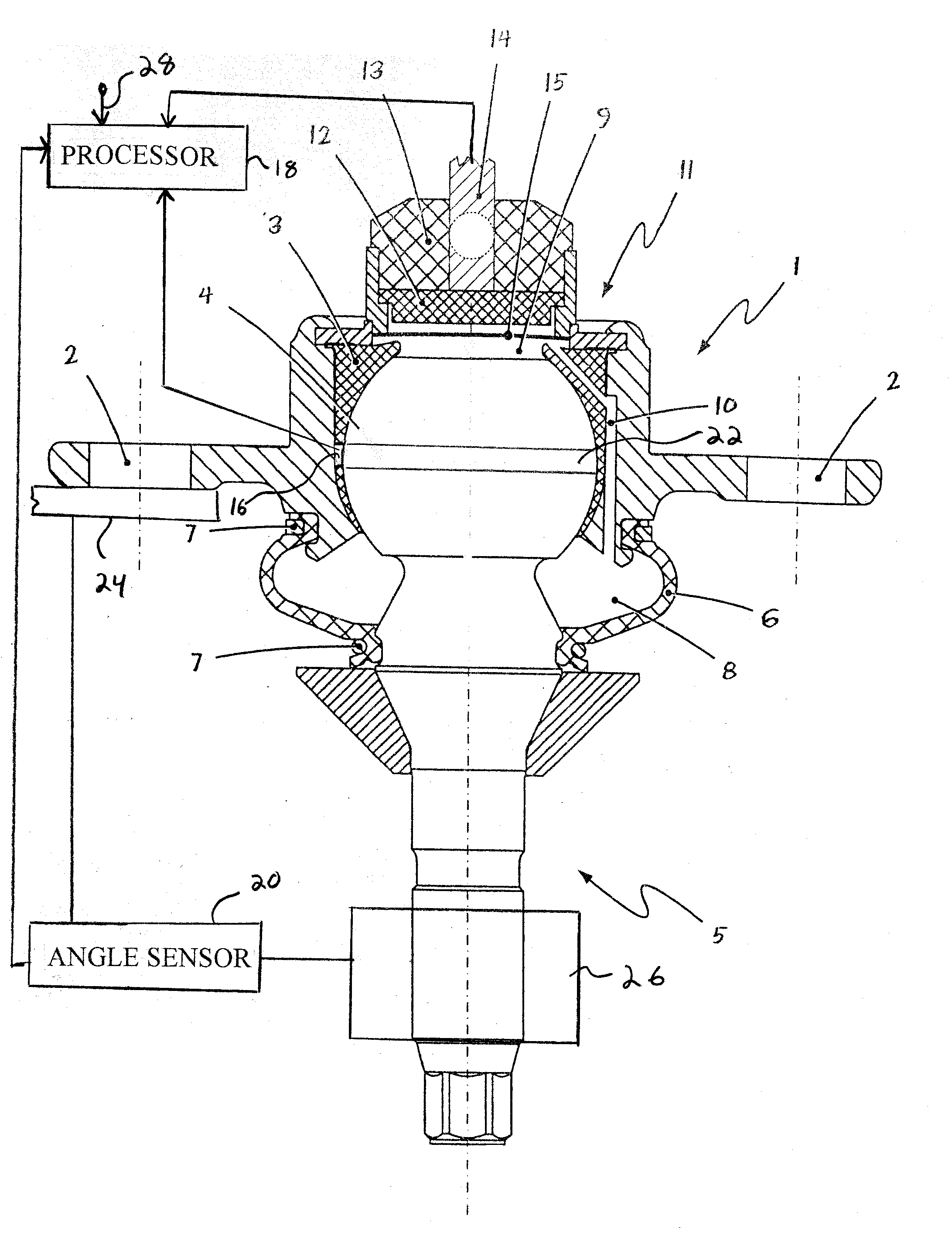
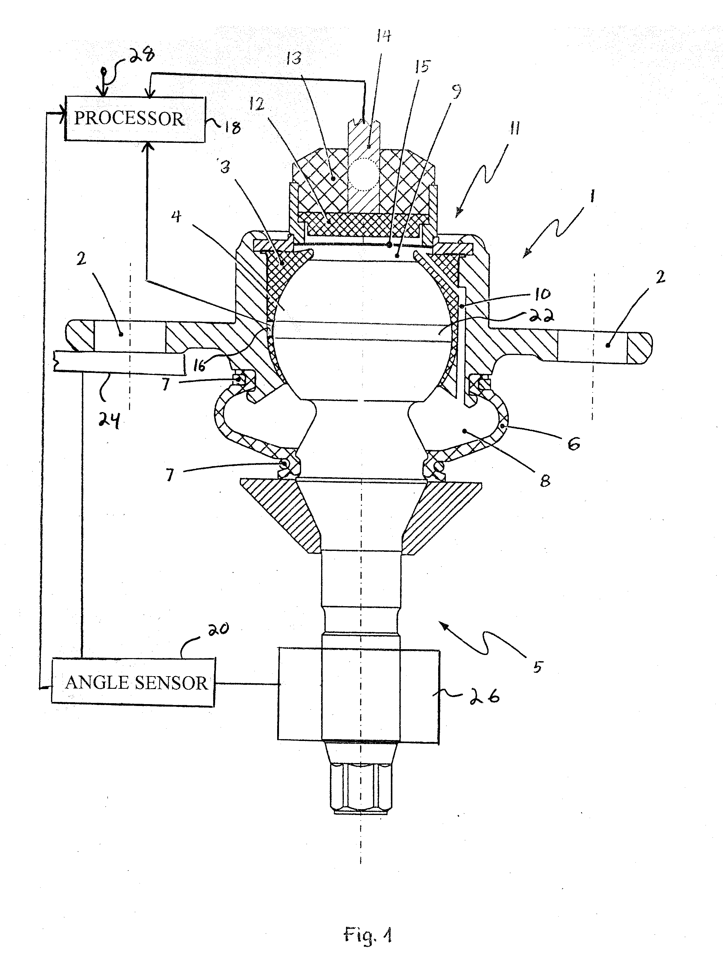
[0032]Referring to the drawings, FIG. 1 shows, in a schematic longitudinal section, an embodiment of a ball and socket joint according to the present invention. The essentially pot-shaped joint housing 1 with fastening flanges 2 as well as with the joint shell or ball shell 3 arranged in the joint housing are detected at first. The ball 4 of a ball pivot 5 is in turn arranged in the interior space of the ball shell 3.

[0033]Furthermore, an elastomer sealing bellows 6 is shown, which is connected to the shaft of the ball pivot 5 as well as to a groove on the joint housing 1 by means of lock washers 7 in such a way that it is tightly in contact with the shaft. The sealing bellows 6 encloses in its interior space 8 a certain volume, which may be filled, in general, with air, or partly also with a lubricant. As has been found, a change (mostly a reduction) occurs in the volume 8 enclosed in the interior space of the sealing bellows 6 during pivoting motions of the ball pivot 5 in relatio...


PUM


Abstract

A ball and socket joint, for example, for an axle system of a motor vehicle. The ball and socket joint has an essentially ring-shaped or pot-shaped joint housing (1), in the essentially cylindrical interior space of which a ball shell (3) is arranged. The ball (4) of a ball pivot is accommodated in the ball shell (3) in a slidingly movable manner. The ball and socket joint has, furthermore, a sealing bellows (6) as well as a sensor means for monitoring the tightness of the ball and socket joint.

Description

CROSS REFERENCE TO RELATED APPLICATION[0001]This is a continuation of and claims the benefit (35 U.S.C. §120 and 365(c)) of copending International Application PCT / DE2006 / 001018 of 14 Jun. 2006, which designated inter alia the United States and which claims the priority of German Application DE 10 2005 027 825 of 15 Jun. 2005. The entire contents of each application is hereby incorporated by reference in its entirety.FIELD OF THE INVENTION[0002]The present invention pertains to a ball and socket joint with a sensor means for monitoring the tightness, especially for an axle system or a wheel suspension of a motor vehicle. The ball and socket joint has an essentially ring-shaped or pot-shaped joint housing, in the essentially cylindrical interior space of which a ball shell is arranged. The ball of a ball pivot is accommodated in the ball shell in a slidingly movable manner. The ball and socket joint having, furthermore, a sealing bellows between the joint housing and the ball pivot. ...

Claims


Application Information

Patent Timeline
IPC IPC(8): F16C11/06G05B11/36
CPCF16C11/0647Y10T403/32721G01M3/3263G01M3/26B60G2204/416F16C11/06F16C11/00
Inventor KRUSE, JOCHENSPRATTE, JOACHIMKLANK, MICHAEL
Owner ZF FRIEDRICHSHAFEN AG
Learn More