Air-Cooled Fuel Cell System

a fuel cell and air-cooled technology, applied in the field of air-cooled, can solve the problems of difficult to cool down air-cooled fuel cells without the output reduction, fuel cell output may reduce, etc., and achieve the effect of reducing the amount of power generation, reducing the output of fuel cells, and increasing the amount of air for power generation

Inactive Publication Date: 2008-08-14
TOYOTA JIDOSHA KK
View PDF3 Cites 22 Cited by
  • Summary
  • Abstract
  • Description
  • Claims
  • Application Information

AI Technical Summary

Benefits of technology

[0006]In some fuel cell, if it reaches a too high temperature, the amount of power generation decreases in accordance with an increase in the supply of the oxidizing gas. In the conventional technology, if the amount of the air for cooling is increased, the amount of the air for power generation is also increased. Thus, in the end, if the fuel cell is cooled down by controlling the volume of the air blown by the blower, this cooling of the fuel cell may reduce the output of the fuel cell. In other words, the conventional technology has such a technical problem that it is difficult to cool down the air-cooled fuel cell without the output reduction.

Problems solved by technology

Thus, in the end, if the fuel cell is cooled down by controlling the volume of the air blown by the blower, this cooling of the fuel cell may reduce the output of the fuel cell.
In other words, the conventional technology has such a technical problem that it is difficult to cool down the air-cooled fuel cell without the output reduction.

Method used


Image

  • Air-Cooled Fuel Cell System
  • Air-Cooled Fuel Cell System
  • Air-Cooled Fuel Cell System

Examples


Embodiment Construction

[0050]The preferable embodiment of the present invention will be discussed with reference to the drawings hereinafter.

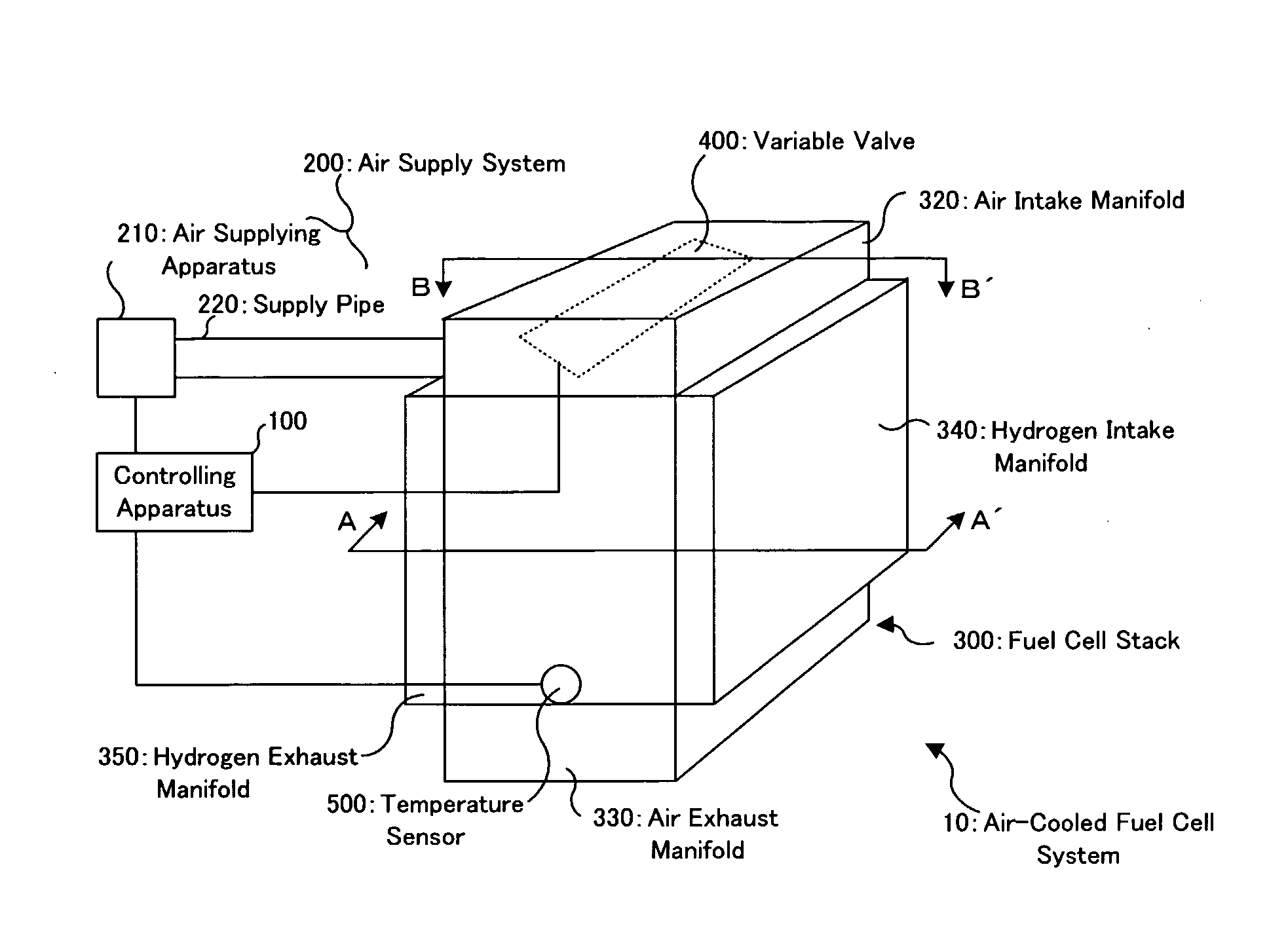
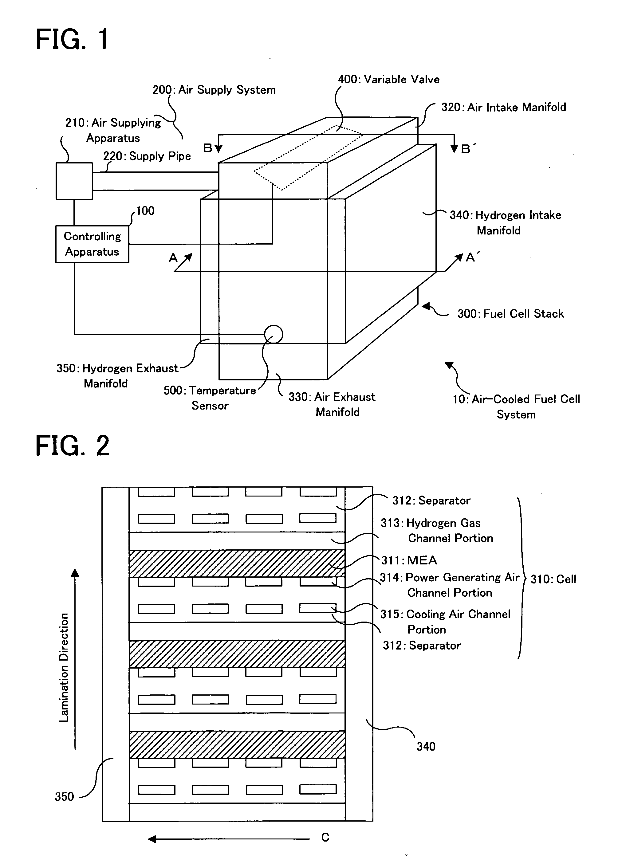
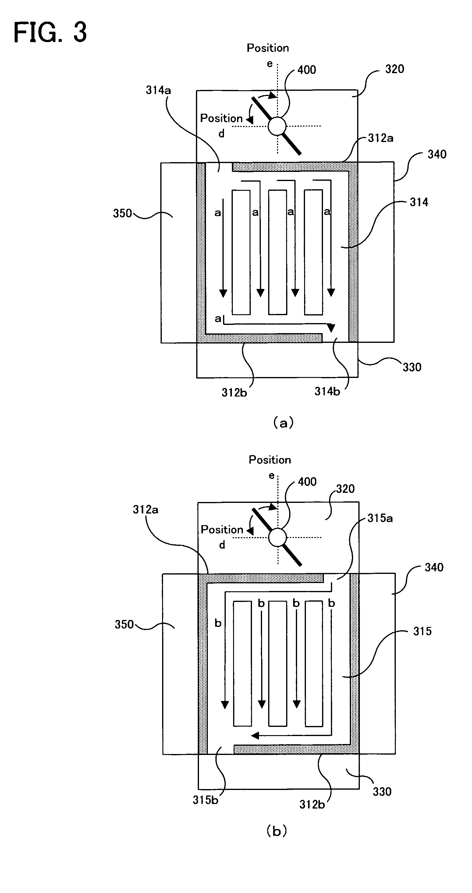
[0051]At first, with reference to FIG. 1 to FIGS. 3, as occasion demands, the structure of an air-cooled fuel cell system according to the embodiment of the present invention will be discussed. FIG. 1 is a schematic perspective view showing an air-cooled fuel cell system 10. FIG. 2 is an A-A′ cross sectional view in FIG. 1. FIGS. 3 are B-B′ cross sectional views in FIG. 1.

[0052]In FIG. 1, the air-cooled fuel cell system 10 is provided with: a controlling apparatus 100; an air supply system 200; a fuel cell stack 300; a variable valve 400; and a temperature sensor 500.

[0053]The controlling apparatus 100 is a control unit for controlling the operation or operations of the air-cooled fuel cell system 10, and is constructed to function as one example of the “controlling device” of the present invention.

[0054]The air supply system 200 is provided with: an air supplying ap...


PUM

PropertyMeasurementUnit
temperatureaaaaaaaaaa
threshold temperatureaaaaaaaaaa
volumeaaaaaaaaaa

Abstract

In an air-cooled fuel cell system (10), a controlling apparatus (100) performs a temperature controlling process on the basis of the temperature of a fuel cell detected by a temperature sensor (500). At this time, if the cell temperature is greater than a target temperature Ta and if the cell temperature is less than a threshold temperature Tth for defining a boundary between (i) a temperature group TG1, in which a change in a cell voltage is small relative to the stoichiometric ratio of the air for power generation, and (ii) a temperature group TG2, in which a change in the cell voltage is large relative to the stoichiometric ratio of the air for power generation, the controlling apparatus (100) controls an air supplying apparatus (210) to increase the amount of the air supplied to an air intake manifold (320). If the cell temperature is equal to or greater than the threshold temperature Tth, the controlling apparatus (100) controls a variable valve (400) to increase the amount of the air flowing into a cooling air channel portion (315) without an increase in the amount of the air flowing into a power generating air channel portion 314.

Description

TECHNICAL FIELD[0001]The present invention relates to an air-cooled (i.e., an air cooled-type or air cooling type) fuel cell system provided with an air-cooled fuel cell which uses an oxidizing gas for power generation and cooling.BACKGROUND ART[0002]As this type of air-cooled fuel cell system, there is proposed a system in which air used for a cell reaction and air used for cooling are supplied in a common air supply route (e.g. refer to Patent document 1).[0003]According to the air-cooled fuel cell disclosed in the Patent document 1 (hereinafter referred to as a “conventional technology”), it is considered that it is possible to quickly restore or bring the temperature of the fuel cell back to a set value by controlling the volume of the air blown by a blower.[0004]Incidentally, there is also proposed another technology in which one portion of the air used for cooling in the fuel cell is used as the air for power generation (refer to Patent document 2).[0005]Moreover, in the fuel ...

Claims


Application Information

Patent Timeline
Patent Type & Authority Applications(United States)
IPC IPC(8): H01M8/04
CPCH01M8/0267H01M8/04014H01M8/04067Y02E60/50H01M8/04753H01M8/04776H01M2008/1095H01M8/0432H01M8/0258H01M8/04
Inventor MURATA, SHIGEAKINAKANISHI, HARUYUKI
Owner TOYOTA JIDOSHA KK
Why Eureka
Try Eureka