Surgical Positioning Device

a positioning device and positioning technology, applied in the field of surgical positioning devices, can solve the problems of deteriorating quality, unclear image, marker image identification,

Inactive Publication Date: 2008-08-14
YANG BEEN DER +2
View PDF4 Cites 8 Cited by
  • Summary
  • Abstract
  • Description
  • Claims
  • Application Information

AI Technical Summary

Benefits of technology

[0010]An objective of the present invention is to provide a surgical positioning device used in image guided surgery. By using the surgical positioning device of the invention, users may produce satisfactory CT images on which fiducial markers are bright enough but produce no artifact. Instead of utilizing the conventional try-and-error approach, the present invention proposes a rational and systematic way to calibrate the quality of an object under CT analysis.
[0019]Based on the formulation provided above, potential fiducial markers may be identified with ease. For example, aluminum oxide (Al2O3), whose estimated CT number is 2,719, demonstrates great suitability as it produces almost no “metal artifact” on CT scan; similarly, silicon nitride (Si3N4), which has an estimated CT number of 2,861, shows a desirable result on CT scan as well. The relatively low error percentages (both less than 1%) between the estimated CT numbers and the experimental ones of the aluminum oxide and silicon nitride validate the soundness of the present invention, making it a reliable solution for the fabrication of surgical positioning devices.

Problems solved by technology

Conventionally, steel balls are commonly used in scanning due to their availability; however, the inherent “metal artifact” inevitably interferes the clarity of the image and deteriorates the quality thereof.
In some situations, the artifact is so severe that it not only causes marker image identification problems but also obstructs the subsequent diagnosis.
However, several unsolved problems keep these inventions from being fully accepted.
As to the latter two, problems resulted from unequal mixture will always have to be overcome before they can be successfully reduced to practice.
Besides, all the three inventions, which largely depend on an empirical approach to find suitable material, fail to provide a systematic way to identify the eligible material.

Method used


Image

  • Surgical Positioning Device
  • Surgical Positioning Device
  • Surgical Positioning Device

Examples


Embodiment Construction

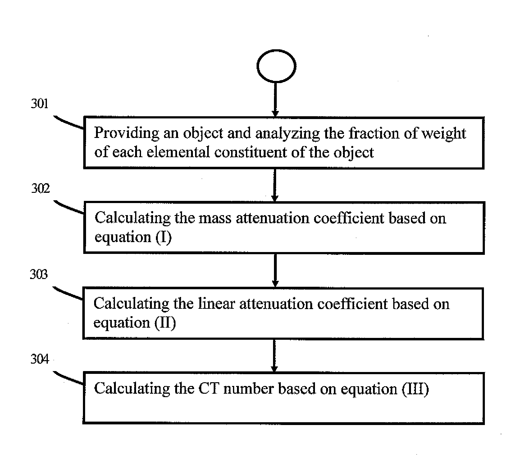
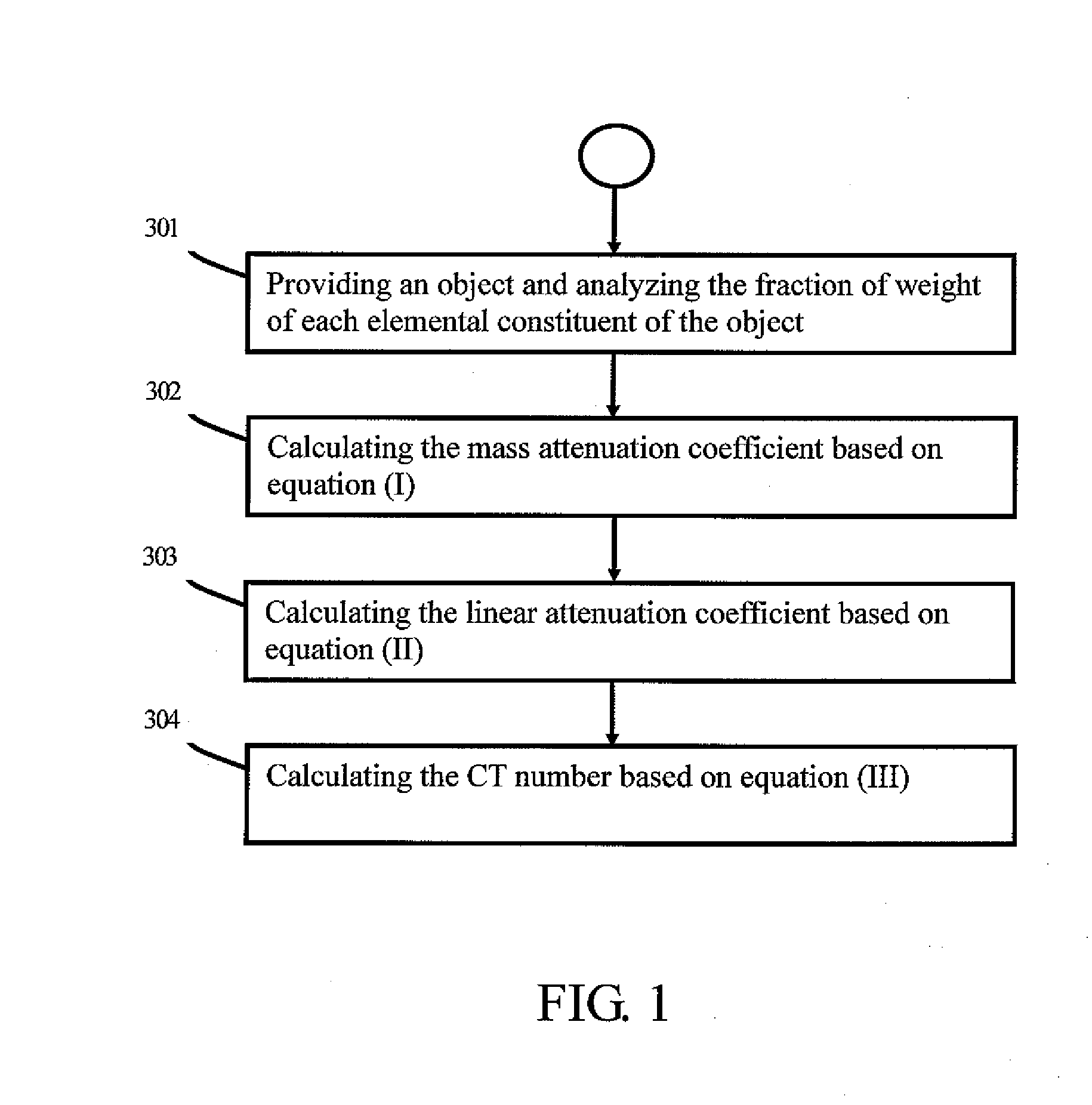
[0027]Please refer to FIG. 1 for a flowchart of the formulation of the present invention.[0028]Step 301: Providing an object and analyzing the fraction of weight of each elemental constituent of the object.

[0029]First of all, an object of interest is provided with the fraction of weight of each ingredient calculated. Since the analysis of chemical components is a well-established art, further elaboration is omitted hereby.[0030]Step 302: Calculating the mass attenuation coefficient based on equation (I) as follows:

μ / ρ=∑iwi(μ / ρ)i,equation(I)

[0031]wherein wi and (μ / ρ)i stand for the fraction of weight and the mass attenuation coefficient of the ith atomic constituent respectively.[0032]Step 303: Calculating the linear attenuation coefficient based on equation (II) as follows:

μ=(μ / ρ)ρ  equation (II),

[0033]wherein μ is the linear attenuation coefficient; ρ is the density of the object.[0034]Step 304: Calculating the CT number based on the equation (III) as follows:

CT=1,000μ-μwaterμwater...


PUM


Abstract

A surgical positioning device comprises a main part and at least three fiducial markers. Said fiducial markers have a CT number ranging from 1,000 to 3,000 and may produce dense, bright, and artifact-free spots on a CT scanning image.

Description

BACKGROUND OF THE INVENTION[0001]1. Field of the Invention[0002]The present invention relates to a surgical positioning device used in image guided surgery. More particularly, the invention relates to a surgical positioning device comprising Computed Tomography (CT) fiducial markers with desirable accuracy and no severe artifact.[0003]2. Description of the Related Art[0004]Image guided surgery is a process by which a surgeon performs an operation under the guidance of a three dimensional volumetric image representing the anatomy of a patient. Compared with the conventional un-guided surgery, the image guided surgery is more reliable in that it provides the benefits of minimal invasiveness and high accuracy.[0005]Among the various image modalities, CT is one of the most popular modalities in image guided surgery. Generally, the first step of CT-guided surgery is the collection of CT scan data, which is done by passing a patient through a CT machine pre-operatively; after that, the da...

Claims


Application Information

Patent Timeline
Patent Type & Authority Applications(United States)
IPC IPC(8): A61B6/03
CPCA61B6/12A61B19/54A61B6/14A61B90/39
Inventor YANG, BEEN-DERWANG, JAW-LINWANG, YAO-HUNG
Owner YANG BEEN DER
Why Eureka
Try Eureka