Methods for Deploying Spinal Motion Preservation Assemblies

a technology of spinal column and assembly, which is applied in the field of spinal column assembly deployment, can solve the problems of reduced gap between adjacent vertebrae, pain, and one or more discs in the spinal column not working as intended, and achieves the physiological function of natural disc structures, preservation of translation, and improved weight bearing and load distribution

Inactive Publication Date: 2008-08-14
TRANS1
View PDF91 Cites 82 Cited by
  • Summary
  • Abstract
  • Description
  • Claims
  • Application Information

AI Technical Summary

Benefits of technology

[0045]Spinal mobility preservation assemblies are disclosed which are configured to comprise a plurality of pivots, that function in conjunction with one or more elastomeric (e.g., semi-compliant; compressible) or spring component (including non-helical springs such as the relatively flat Belleville disc), that are particularly effective in preserving motion in any plane relative to the longitudinal axis of the spine.
[0046]In the context of the present invention, “planes” are defined relative to x,y,z orthogonal axes, where z is the longitudinal axis of the spine. More specifically, rotation about x,y,z and motion about x,y are enabled by a plurality of unconstrained pivot points, and the elastomeric component enables motion in the z direction and serves to dampen axial compression.
[0049]Generally, the assemblies may be inserted axially within the spine, following either partial or complete nucleectomy and through a cannula that is docked against the sacrum, into a surgically de-nucleated disc space, from said access point across a treatment zone. In one aspect of the invention, prosthetic or augmentation materials are introduced, through at least one vertebral body or into at least one disc space. The introduction of the spinal MPA of the present invention is accomplished without the need to surgically create or deleteriously enlarge an existing hole in the annulus fibrosus of the disc, and their deployment therapeutically preserves the physiological function of natural disc structures.
[0050]In one aspect of the invention, risks associated with implant expulsion, migration, or subsidence (that are inherently less for the MPA of the present invention) may be even further mitigated by retention means, e.g., by external, self-tapping threads configured to distribute stress evenly over a large surface area, that engage the vertebral body and secure (i.e., anchor) the implant assemblies therein.
[0051]The screw threads are typical of “cancellous” type bone threads known in the art. The threads are typically cut with generally flat faces on the flights of the thread with the most flat of the faces oriented in the direction of the applied load. In one embodiment, the thread profile generally comprises deep flights with an asymmetric thread form, which provides the advantage of improved weight bearing and load distribution. Threads are formed on root portions and extend as continuous threads from the trailing end to the leading end of the respective threaded sections. The screw threads include multiple revolutions that are spaced apart along the roots by inter-thread spacings. The proximal component and distal component threads are like-handed (i.e. the threads turn in the same direction) so that both screw threads are right-handed or so that both are left-handed.

Problems solved by technology

Unfortunately, for a number of reasons referenced below, for some people, one or more discs in the spinal column will not operate as intended.
Often when the discs are not operating properly, the gap between adjacent vertebral bodies is reduced and this causes additional problems including pain.
The spinal discs serve as “dampeners” between each vertebral body that minimize the impact of movement on the spinal column, and disc degeneration, marked by a decrease in water content within the nucleus, renders discs ineffective in transferring loads to the annulus layers.
In addition, the annulus tends to thicken, desiccate, and become more rigid, lessening its ability to elastically deform under load and making it susceptible to fracturing or fissuring, and one form of degeneration of the disc thus occurs when the annulus fissures or is torn.
The fissure itself may be the sole morphological change, above and beyond generalized degenerative changes in the connective tissue of the disc, and disc fissures can nevertheless be painful and debilitating.
Nevertheless, even a contained disc herniation is problematic because the outward protrusion can press on the spinal cord or on spinal nerves causing sciatica.
Another disc problem occurs when the disc bulges outward circumferentially in all directions and not just in one location.
Mechanical stiffness of the joint is reduced and the spinal motion segment may become unstable, shortening the spinal cord segment.
As the disc “roll” extends beyond the normal circumference, the disc height may be compromised, and foramina with nerve roots are compressed causing pain.
Although these procedures are less invasive than open surgery, they nevertheless suffer the possibility of injury to the nerve root and dural sac, perineural scar formation, re-herniation of the site of the surgery, and instability due to excess bone removal.
Although damaged discs and vertebral bodies can be identified with sophisticated diagnostic imaging, existing surgical interventions and clinical outcomes are not consistently satisfactory.
Furthermore, patients undergoing such fusion surgery experience significant complications and uncomfortable, prolonged convalescence.
This can result in a cartilage injury of the facet joint; disruption of the facet capsule, and facet joint or pars interarticularis fracture.
The force generated by the back muscles results in compression of spinal structures.
Gravitational injuries result from a fall onto the buttocks while muscular injuries result from severe exertion during pulling or lifting.
A serious consequence of the injury is a fracture of the vertebral end plate.
However, if the end plate does not heal, the nucleus can undergo harmful changes.
The disc may collapse or it may maintain its height with progressive annular tearing.
If the annulus is significantly weakened, there may be a rupture of the disc whereby the nuclear material migrates into the annulus or into the spinal canal causing nerve root compression.
In rotation, only 50% of the collagen fibers are in tension at any time, which renders the annulus susceptible to injury.
The spine is particularly susceptible to injury in a loading combination of rotation and flexion.
If the rotation continues, the facet joints can sustain cartilage injury, fracture, and capsular tears while the annulus can tear in several different ways.
Any of these injuries can be a source of pain.
To date, drawbacks of currently contemplated or deployed prosthetic nucleus devices include subsidence; their tendency to extrude or migrate; to erode the bone; to degrade with time, or to fail to provide sufficient biomechanical load distribution and support.
Some of these drawbacks relate to the fact that their deployment typically involves a virtually complete discectomy of the disc achieved by instruments introduced laterally through the patient's body to the disc site and manipulated to cut away or drill lateral holes through the disc and adjoining cortical bone.
The endplates of the vertebral bodies, which comprise very hard cortical bone and help to give the vertebral bodies needed strength, are usually weakened or destroyed during the drilling.
If these structures are injured, it can lead to deterioration of the disc and altered disc function.
Not only do the large laterally drilled hole or holes compromise the integrity of the vertebral bodies, but the spinal cord can be injured if they are drilled too posterior.
Axial compression of a disc results in increased pressure in the disc space.
In general, the disc is more susceptible to injury during a twisting motion, deriving its primary protection during rotation from the posterior facet joints; however, this risk is even greater if and when the annulus is compromised.
Moreover, annulus disruption will remain post-operatively, and present a pathway for device extrusion and migration in addition to compromising the physiological biomechanics of the disc structure.
The result of subsidence is that the effective length of the vertebral column is shortened, which can subsequently cause damage to the nerve root and nerves that pass between the two adjacent vertebrae.

Method used


Image

  • Methods for Deploying Spinal Motion Preservation Assemblies
  • Methods for Deploying Spinal Motion Preservation Assemblies
  • Methods for Deploying Spinal Motion Preservation Assemblies

Examples


first example

[0085]The present invention will now be described more fully hereinafter with reference to accompanying drawings in order to disclose selected illustrative embodiments. This invention may, however, be embodied in many different forms and should not be construed as limited to the embodiments set forth herein; rather these embodiments are provided so that the disclosure can be thorough and complete, and as part of the effort to convey the scope of the invention to those skilled in the art. Like numbers refer to like elements throughout.

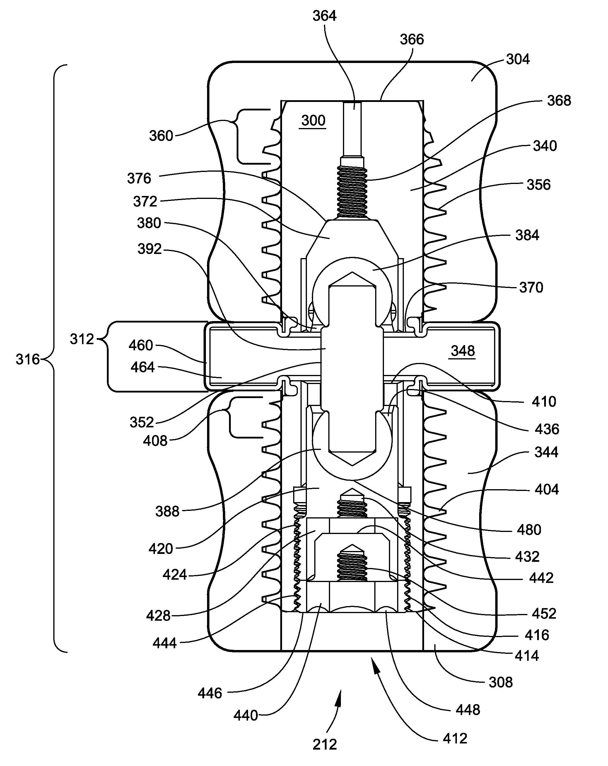
[0086]In order to avoid the imprecision that can sometimes be introduced into a patent application while discussing many different alternative configurations at once, FIG. 3 starts with one very specific embodiment of the present invention. In order to provide an overview of the components and their placement with respect to a spinal motion segment, the explanation will start with an overview of an implanted device. Subsequent drawings will provide deta...


PUM

PropertyMeasurementUnit
aspect ratioaaaaaaaaaa
thicknessaaaaaaaaaa
elongationaaaaaaaaaa

Abstract

Spinal motion preservation assemblies adapted for use in a spinal motion segment are disclosed including the process for delivering and assembling the spinal motion preservation assemblies in the spinal motion segment via an axial channel created with a trans-sacral approach. The spinal motion preservation assemblies make use of a dual pivot. A number of different embodiments of spinal motion preservation assemblies are disclosed which include at least one component adapted for elastic deformation under compressive loads. The disclosed mobility preservation assemblies provide for dynamic stabilization (DS) of the spinal motion segment.

Description

BACKGROUND OF THE INVENTION[0001]This application is a divisional of U.S. patent application Ser. No. 11 / 256,810 filed Oct. 24, 2005 for Spinal Motion Preservation Assemblies and as such claims priority to the '810 application and incorporates it by reference. The '810 application claims priority and incorporates by reference a then co-pending and commonly assigned U.S. Provisional Application No. 60 / 621,148 filed Oct. 22, 2004 for Spinal Mobility Preservation Assemblies and second co-pending and commonly assigned U.S. Provisional Application No. 60 / 621,730 filed Oct. 25, 2004 for Multi-Part Assembly for Introducing Axial Implants into the Spine. This application claims priority and incorporates by reference four co-pending and commonly assigned U.S. patent application Ser. Nos. 10 / 972,184, 10 / 927,039, 10 / 972,040, and 10 / 972,176 all filed on Oct. 22, 2004. These four applications claim priority to two provisional applications 60 / 558,069 filed Mar. 31, 2004 and 60 / 513,899 filed Oct. ...

Claims


Application Information

Patent Timeline
Patent Type & Authority Applications(United States)
IPC IPC(8): A61B17/58A61F11/00
CPCA61B17/70A61F2310/00029A61F2/30744A61F2/441A61F2/442A61F2/4425A61F2/4611A61F2/4637A61F2002/30014A61F2002/30075A61F2002/30224A61F2002/30289A61F2002/30331A61F2002/30405A61F2002/30462A61F2002/30495A61F2002/30507A61F2002/3055A61F2002/30563A61F2002/30566A61F2002/30571A61F2002/30579A61F2002/30581A61F2002/30583A61F2002/30588A61F2002/30601A61F2002/30604A61F2002/30649A61F2002/30677A61F2002/3085A61F2002/30863A61F2002/443A61F2002/444A61F2002/4495A61F2002/4627A61F2002/4629A61F2210/0061A61F2210/0085A61F2220/0025A61F2220/0033A61F2220/0075A61F2230/0069A61F2230/0091A61F2250/0018A61F2310/00017A61F2/30742A61B17/025A61B17/8888A61B2017/0256A61F2002/30327A61F2002/30859A61F2250/0039
Inventor AINSWORTH, STEPHEN D.ASSELL, ROBERT L.DICKHUDT, EUGENE A.WESSMAN, BRADLEY J.
Owner TRANS1
Why Eureka
Try Eureka