[0002]When a stent is to be delivered to a stenting site through a tortuous body lumen, at the distal end of a catheter, the flexibility of the stent enables it to undergo various forms of deformations, for example, bending so that its longitudinal axis is no longer straight but curved, twisting around its longitudinal axis so that its ends rotate relative to each other with the longitudinal axis as its axis of rotation, or with compression or extension of the length of the stent along its longitudinal axis as it moves with the bodily tissue in which it is implanted. Clearly, the more force it takes to deform the stent, the more difficult it is to advance the catheter
delivery system, including the stent, along the tortuous lumen, and the higher the risk of damage to the walls of the lumen.
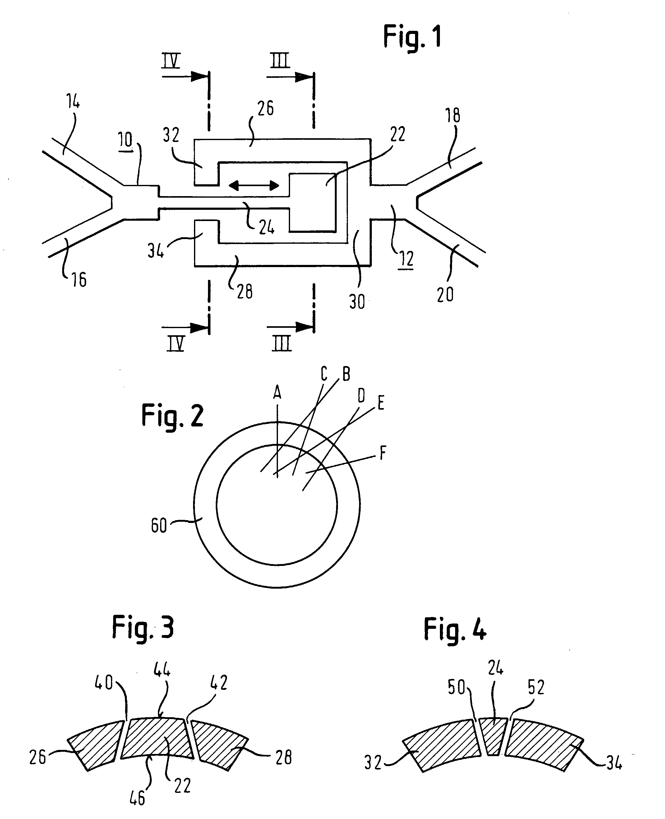
[0005]The essence of the present invention is to use a joint, either to avoid strain in a flexible connector, or to reduce such strain. Characteristic of any joint in accordance with the present invention are first and second facing joint surfaces between which there is relative translational movement. The first
joint surface is on a first structural portion of the stent matrix and the second
joint surface is on a second structural portion of the stent matrix, so that relative movement between the first and second structural portions can be accommodated by the said translational movement without requiring elastic or plastic deformation of any part of the stent. If there is no elastic or plastic deformation, then there is no
resultant forces imposed by the stent on the bodily tissue.
[0009]In consequence, surfaces facing each other across a line of a
laser cut are free to slide face-to-face relative to each other radially in and out with reference to the said
long axis. However, if one were to move the workpiece relative to the
laser so the laser beam no longer passes through the
long axis of the tubular workpiece, the potential for face-to-face sliding would exist in some other plane, not radial to the
long axis. Going a step further, one can envisage a joint in which the joint surfaces have been laser
cut in more than one relative orientation, deliberately to set up a steric hindrance to face-to-face sliding, in every direction except the one which is desired of the joint being created. In this way,
computer control of the movement of the workpiece relative to the laser beam can create not only the stent matrix but also a plurality of joints between portions of the stent matrix which should be able to move, in use, relative to each other to relieve stresses within the stent matrix, yet also serve to maintain the
mechanical integrity of the stent matrix, end-to-end.
[0012]Another embodiment of the present invention is manifested in a method of making a flexible stent from tube stock, which is characterized by forming a sliding joint within the strut matrix. Such a joint can be made by
cutting joint lines through the wall thickness of the tube stock, said joint lines including portions that do not project through the longitudinal central tube axis of the tube stock. The use of such “off-axis” cuts allows steric hindrance between the two tube stock portions, one each side of the sliding surfaces of the joint, to frustrate any tendency of the portions to separate from each other along the
joint line.
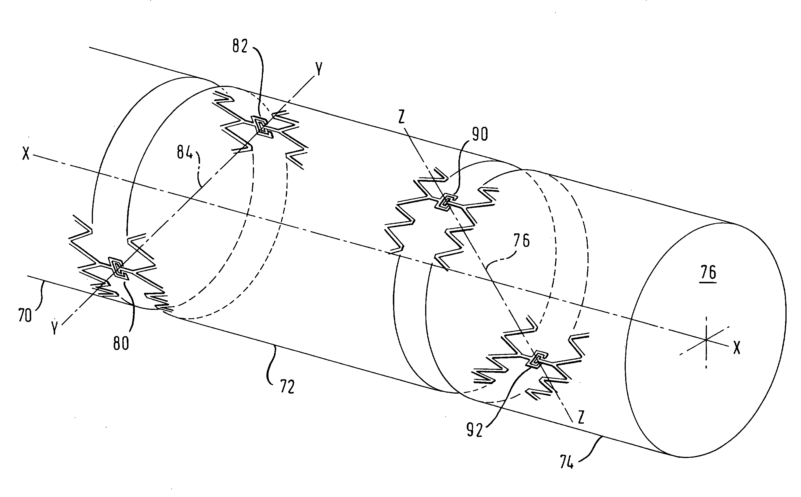
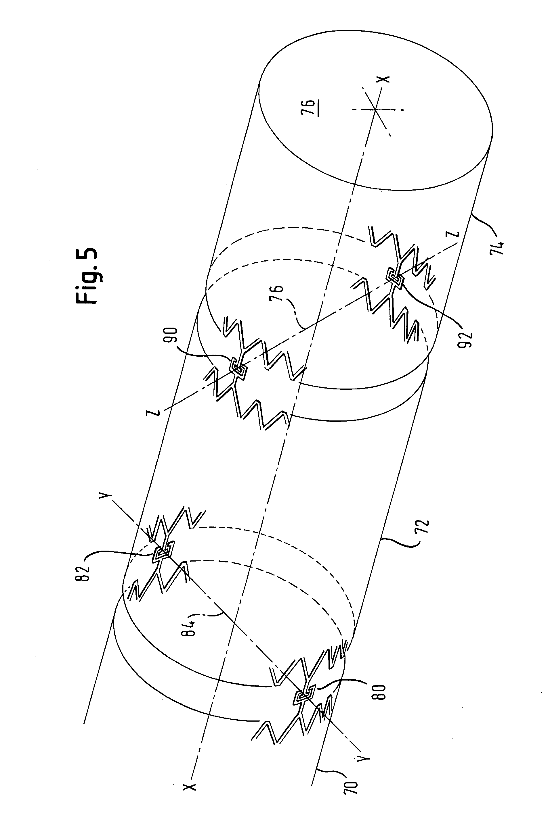
[0013]Besides movements of the tube stock portions in a movement parallel to the longitudinal axis, the use of such slide joints also allows the rotation of the tube stock portion about a short (radial) axis perpendicular to the longitudinal axis of the tube stock. This is possible due to some play between the first node and second node (perhaps due to manufacturing tolerances and the gap produced by the laser) that allows for some hinging movement about the longitudinal axis of the sliding joint. Thus, an arrangement of sliding joints in diametrically opposite pairs, with each structural stent ring of a stenting tube having an
axial length between first and second ends of the ring, and with each such ring end jointed by a pair of sliding joints to an adjacent end of the next adjacent stent ring, with one such joint at each end of a
diameter to the stent lumen. The defining
diameter of the pair of joints at one end of each stent ring is displaced by, say, 90° from the defining
diameter of the pair of joints at the other end of the same stenting ring, so as to give a stent made up of a string of such rings the flexibility to bend in all directions away from a straight line on the long central axis of the lumen of the stent.

