Exhaust Gas Purification System For Internal Combustion Engine

a technology for exhaust gas purification and internal combustion engines, which is applied in the direction of machines/engines, mechanical equipment, electric control, etc., can solve the problems of difficult to perform the high-pressure pm filter regeneration process while the vehicle is moving, and the temperature of the particulate filter is likely to rise excessively, so as to suppress the excessive temperature rise of the particulate filter, increase the effect of exhaust gas pressure, and reduce the pressure inside the particulate filter

Inactive Publication Date: 2008-08-21
TOYOTA JIDOSHA KK
View PDF0 Cites 31 Cited by
  • Summary
  • Abstract
  • Description
  • Claims
  • Application Information

AI Technical Summary

Benefits of technology

[0004]The present invention has been made in view of the above described circumstances and has as an object to provide a technique to perform the high pressure PM filter regeneration process while suppressing excessive temperature rise of a particulate filter in an exhaust gas purification system for an internal combustion engine that is adapted to perform the high pressure PM filter regeneration process, even during the time in which running conditions of the internal combustion engine can easily change as is the case when the vehicle is moving.
[0045]If this is done, the exhaust gas pressure in the upstream of the exhaust throttle valve increases, and therefore, it is possible to increase the exhaust gas pressure acting on the internal combustion engine while increasing the pressure inside the particulate filter. Consequently, it is possible to activate exhaust brake and regenerate the particulate matter trapping capacity of the particulate filter earlier.

Problems solved by technology

If the high pressure PM filter regeneration process is performed while running conditions of the internal combustion engine are varying every second as is the case when the vehicle equipped with that engine is moving, it is highly likely that the temperature of the particulate filter rises excessively.
For this reason, it has been difficult to perform the high pressure PM filter regeneration process while the vehicle is moving.

Method used


Image

  • Exhaust Gas Purification System For Internal Combustion Engine
  • Exhaust Gas Purification System For Internal Combustion Engine
  • Exhaust Gas Purification System For Internal Combustion Engine

Examples


first embodiment

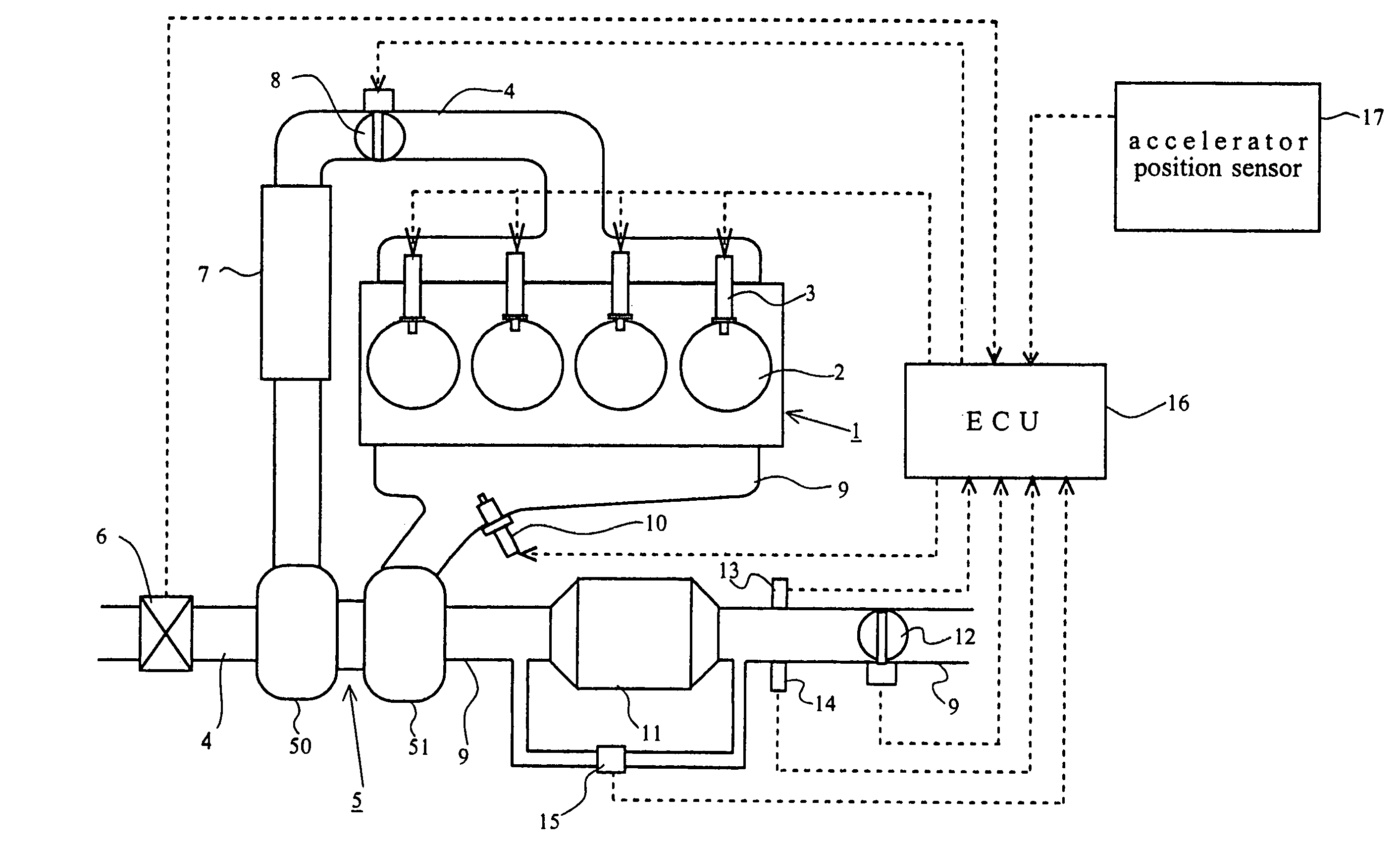
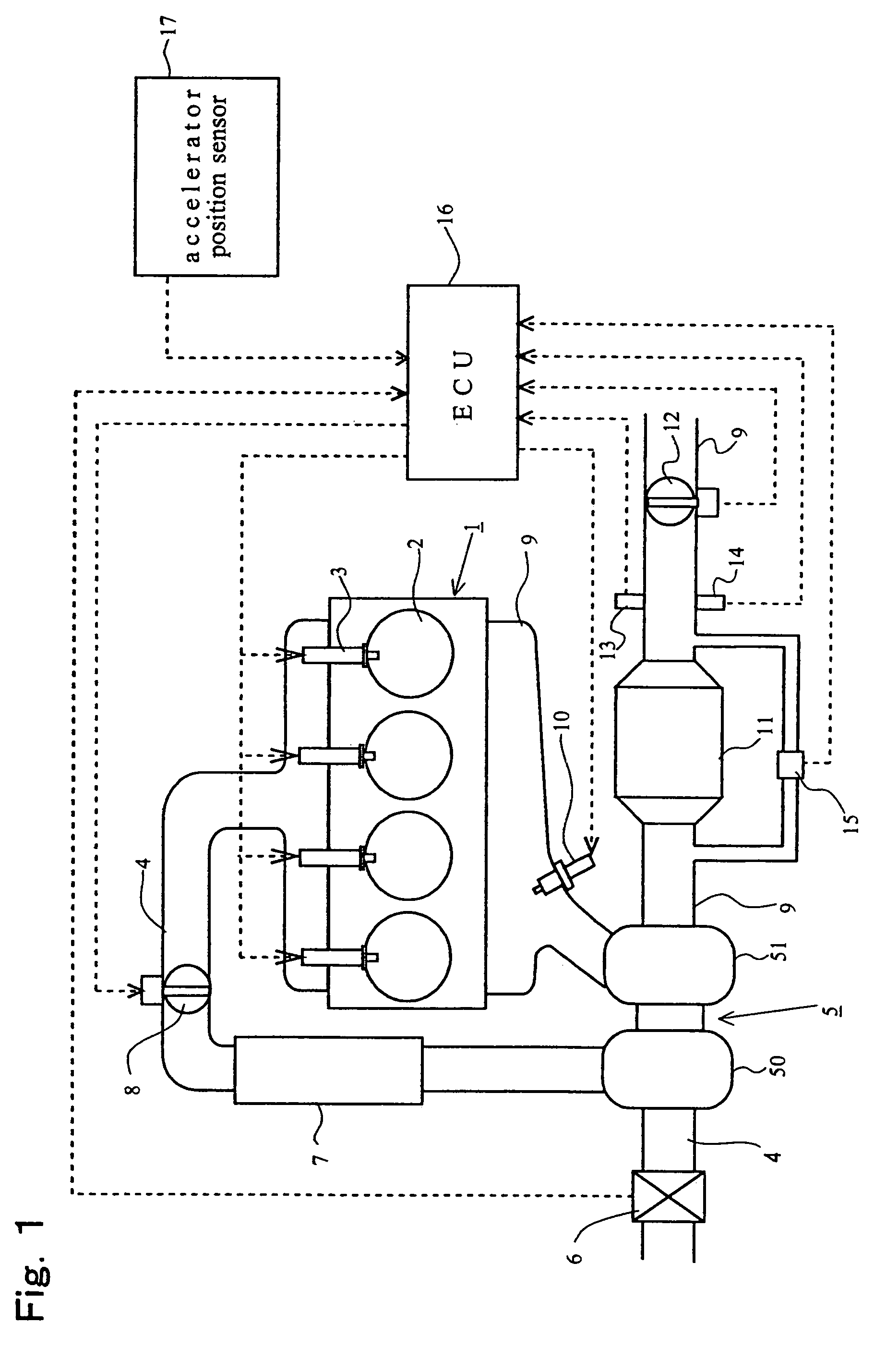
[0064]A first embodiment of the present invention will be described with reference to FIGS. 1 through 12. FIG. 1 is a diagram schematically showing the structure of an internal combustion engine to which the present invention is applied.

[0065]The internal combustion engine 1 shown in FIG. 1 is a compression ignition type internal combustion engine that is driven using light oil as fuel (i.e. a diesel engine). The internal combustion engine 1 has a plurality of cylinders 2, each of which is provided with a fuel injection valve 3 that injects fuel directly into the cylinder 2.

[0066]The internal combustion engine 1 is connected with an intake passage 4. In the intake passage 4 is provided a compressor housing 50 of a centrifugal supercharger (or a turbocharger) 5. An air flow meter 6 is provided in the intake passage 4 upstream of the compressor housing 50. An intake air cooler (i.e. intercooler) 7 is provided in the intake passage downstream of the compressor housing 50. An intake thr...

second embodiment

[0144]Next, a second embodiment of the exhaust gas purification system according to the present invention will be described with reference to FIGS. 13 to 14. Here, only structures that are different from the above described first embodiment will be described, and descriptions of structures similar to those in the first embodiment will be omitted.

[0145]FIG. 13 is a diagram schematically showing the structure of an internal combustion engine 1 according to this embodiment. In FIG. 13. a flow rate regulation valve 18 is provided in the exhaust passage 9 upstream of the particulate filter 11. The flow rate regulation valve 18 is adapted to be controlled electrically by the ECU 16. In addition, an exhaust brake switch 19 is connected to the ECU 16.

[0146]When the exhaust brake switch 19 is turned on, the ECU 16 controls to decrease the degree of opening of the exhaust throttle valve 12. A decrease in the degree of opening of the exhaust throttle valve 12 leads to an increase in frictions ...


PUM


Abstract

The present invention is directed to an exhaust gas purification system for an internal combustion engine that performs high pressure PM filter regeneration process by decreasing the degree of opening of an exhaust throttle valve in regenerating the particulate matter trapping capacity of a particulate filter and has as an object to provide a technology that enables to perform the high pressure PM filter regeneration process while suppressing excessive temperature rise of the particulate filter even while the vehicle is moving. According to the invention, a prediction is made, when the high pressure PM filter regeneration process is performed, as to whether there is a possibility that the temperature of the particulate filter will reach a predetermined upper limit temperature, and the pressure inside the particulate filter is controlled in accordance with the prediction.

Description

FIELD OF THE INVENTION[0001]The present invention relates to a technology for regenerating the particulate matter (PM) trapping capacity of a particulate filter.BACKGROUND OF THE INVENTION[0002]Japanese Patent Application Laid-Open NO. 2001-317333 discloses a process of regenerating the PM trapping capacity of a particulate filter while increasing the pressure inside the particulate filter by decreasing the degree of opening of an exhaust throttle valve provided in an exhaust passage downstream of the particulate filter (which process will be hereinafter referred to as the high pressure PM filter regeneration process). Japanese Utility Model Application Laid-Open No. 4-008718 and Japanese Patent Application Laid-Open No. 2003-120263 also disclose technologies related to regeneration of the PM trapping capacity of a particulate filter.SUMMARY OF THE INVENTION[0003]If the high pressure PM filter regeneration process is performed while running conditions of the internal combustion engi...

Claims


Application Information

Patent Timeline
Patent Type & Authority Applications(United States)
IPC IPC(8): F01N3/00
CPCF01N3/023F01N3/0235F01N9/002F01N2240/36F01N2260/12Y02T10/47F01N2560/08F02B37/00F02D41/029F02D41/123F02D2200/0804F01N2260/14Y02T10/40
Inventor HASHIZUME, TAKESHI
Owner TOYOTA JIDOSHA KK
Why Eureka
Try Eureka