Refrigerator accelerated heat exchanger

a heat exchanger and refrigerator technology, applied in the field of refrigerators, can solve the problems of increasing the energy consumption of the appliance, and clogging and closing the flow passages of cooling air, so as to accelerate the movement of air through the air flow passages and reduce the cross-sectional diameter.

Inactive Publication Date: 2008-08-21
WHIRLPOOL CORP
View PDF13 Cites 14 Cited by
  • Summary
  • Abstract
  • Description
  • Claims
  • Application Information

AI Technical Summary

Benefits of technology

[0011]The present invention is directed to a refrigerator tube and fin-type accelerated airflow heat exchanger having a dividing wall that bifurcates the heat exchanger into first and second air flow passages. Fins on the heat exchanger include apertures therein, allowing for both horizontal and vertical movement of air through the air flow passages. The dividing wall extends through the heat exchanger at an angle, decreasing the cross-sectional diameter of both the first and second airflow passages and resulting in accelerated movement of air through the air flow passages. The heat exchanger may be utilized in a condenser assembly and / or an evaporator assembly. The evaporator assembly may be situated along the back, bottom, top or sidewalls of the freezer compartment of the refrigerator, and preferably includes a fan to aid in air flow through the refrigerator's cooling air circuit. The condenser assembly is situated within a machine compartment of the refrigerator and includes a fan to aid in air flow through condenser coils.

Problems solved by technology

However, if fin density is increased, the normal frost build-up on the fins can clog and close the flow passages for cooling air.
With such an arrangement, more frequent defrosting is required, which significantly increasing energy consumption of the appliance.
Similarly, increasing the flow velocity of the cooling air into the evaporator, such as by increasing the fan speed, results in more energy consumption and increases the overall noise level of the appliance.
Other previous heat transfer enhancement methods have been found to be disadvantageous when applied to refrigerators.
For example, louvered or lanced fins are considered less effective than needed because of the relatively low flow velocities of cooling air in refrigerators and the frost build-up on the louvers.
Additionally, evaporators having trapezoidally shaped fins, such as the evaporator shown in U.S. Pat. No. 5,157,941 issued Oct. 27, 1992, have been found difficult to manufacture.
However, as with fin-type evaporators, a more compact design closes the flow passages and slows the flow of cooling air through the condenser.

Method used


Image

  • Refrigerator accelerated heat exchanger
  • Refrigerator accelerated heat exchanger
  • Refrigerator accelerated heat exchanger

Examples


Embodiment Construction

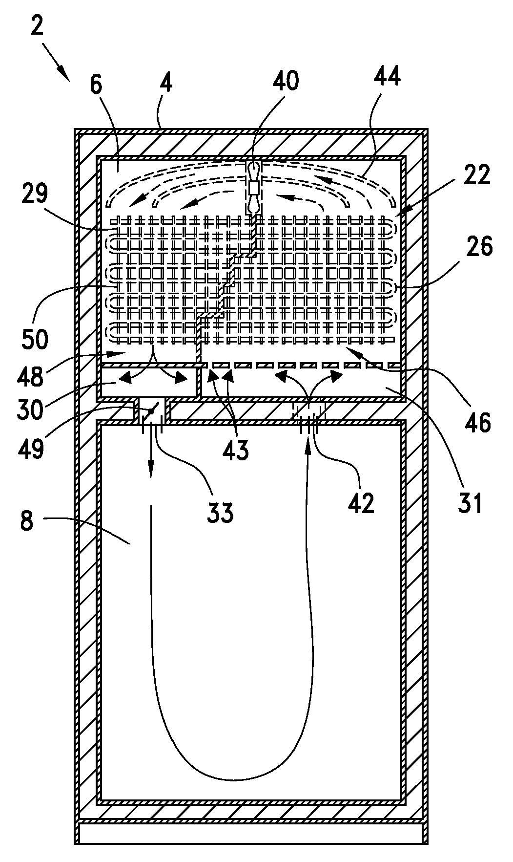
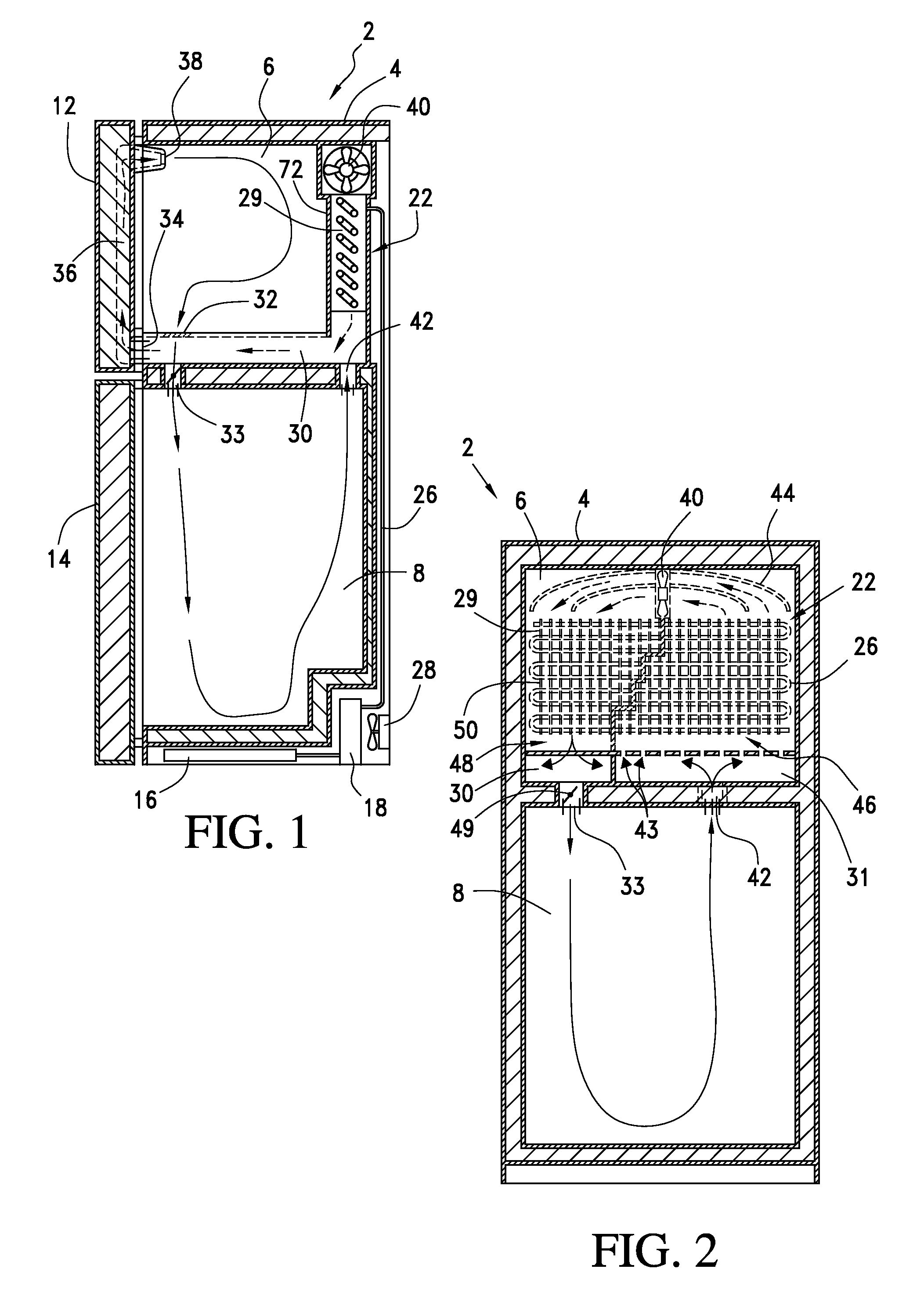
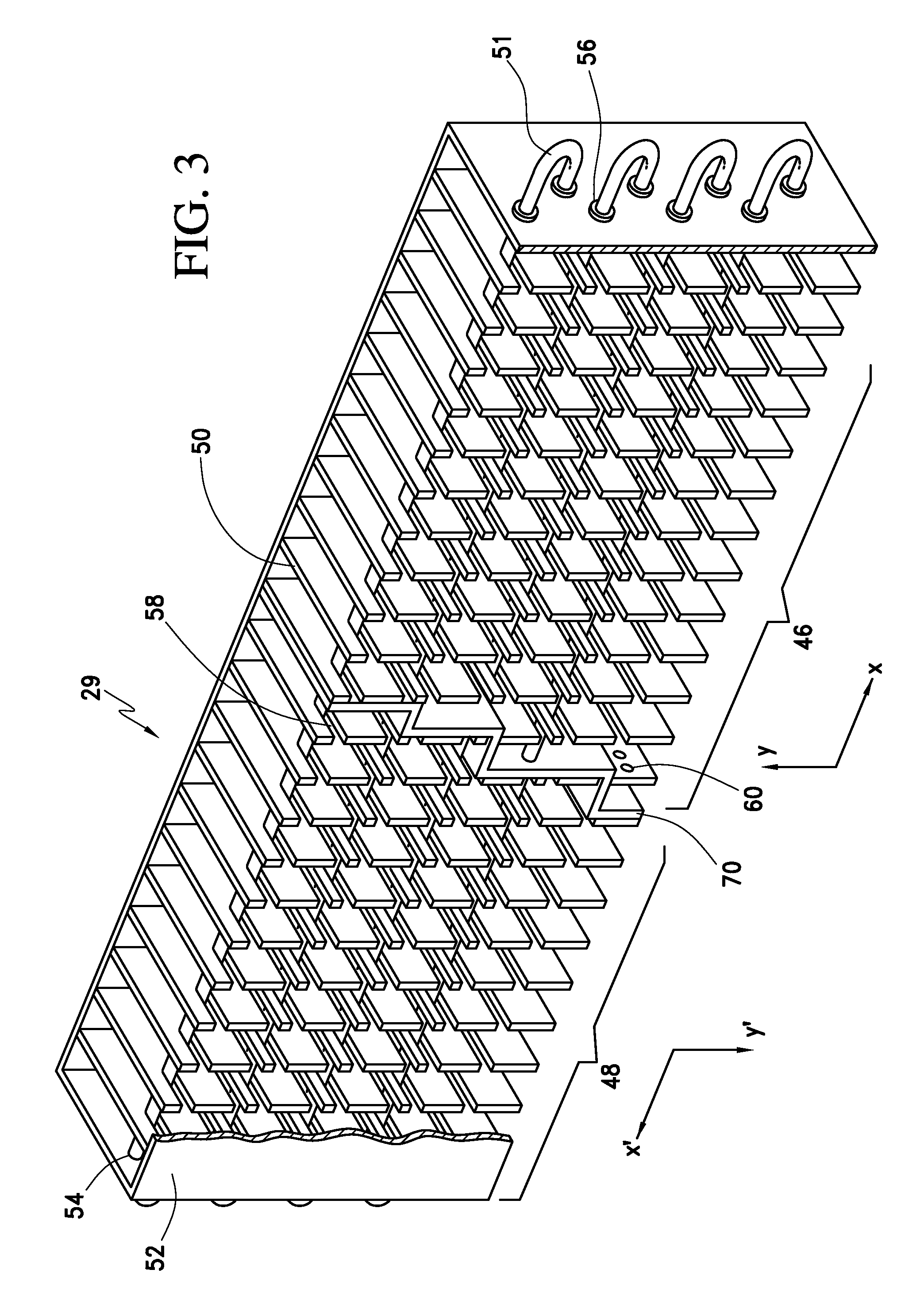
[0028]With initial reference to FIG. 1, a refrigerator 2 includes a cabinet 4 housing two food storage cavities, a first upper cavity 6 and a second lower cavity 8, for storing food or other articles to be cooled or frozen. Cavities 6 and 8 are closed by doors 12 and 14, respectively. In a preferred embodiment, upper cavity 6 constitutes a freezer compartment and lower cavity 8 defines a fresh food compartment. Refrigerator 2 includes an air flow circuit having a condenser assembly 16, a compressor 18, an evaporator assembly 22 and a sealed refrigerant system including tube 26 for connecting these elements. In a manner known in the art, tube 26 contains a refrigerant fluid. Additionally, the air flow circuit preferably includes a condenser fan 28. In accordance with the invention, evaporator assembly 22 includes a tube and fin-type accelerated heat exchanger 29 which will be detailed more fully below.

[0029]In a first arrangement shown in FIGS. 1 and 2, cooled air circulates from eva...


PUM


Abstract

A heat exchanger for a refrigerator includes a dividing wall that bifurcates the heat exchanger into first and second airflow passages. The fins include apertures therein, allowing for both horizontal and vertical movement of air through the heat exchanger. The dividing wall extends through the heat exchanger at an angle, which decreases the cross-sectional diameter of both the first and second airflow passages and results in accelerated air flow through the air passages. In use, air from the refrigerator is directed into the first airflow passage of the heat exchanger for heat exchange, and is then directed by curved baffles into the second airflow passage for further heat exchange. Air exiting the second airflow passage is then directed into a compartment of the refrigerator.

Description

CROSS-REFERENCE TO RELATED APPLICATIONS[0001]The present application represents a continuation-in-part of U.S. patent application Ser. No. 11 / 644,558 entitled “Accelerated Heat Exchanger” filed Dec. 22, 2006, pending.BACKGROUND OF THE INVENTION[0002]1. Field of the Invention[0003]The present invention pertains to the art of refrigerators and, more specifically, to tube and fin-type heat exchangers used in domestic refrigerators.[0004]2. Description of the Related Art[0005]Refrigerators typically include one or more enclosures or chambers for storing food or other articles to be cooled or frozen. The refrigerator housing about these enclosures includes two intersecting fluid circuits: a refrigerant circuit and a cooling air circuit. The refrigerant circuit generally includes a compressor, a condenser and an evaporator with tubing between these elements to permit the flow of the refrigerating fluid. The condenser essentially exchanges heat from the refrigerator interior to the outside...

Claims


Application Information

Patent Timeline
Patent Type & Authority Applications(United States)
IPC IPC(8): F28D15/00F25D11/02F25B39/02F25D17/06F28F1/10
CPCF25B39/022F25B2500/01F25D17/065F25D2317/063F28D1/0477F28D7/08F28D7/085F28F1/006F28F1/32F28F2215/12
Inventor WU, GUOLIANKUEHL, STEVEN J.
Owner WHIRLPOOL CORP
Why Eureka
Try Eureka