
Valve pin guidance and alignment system for an injection molding apparatus

a technology of valve pins and alignment systems, which is applied in the direction of application, food shaping, and food science, etc., can solve the problems of valve pin sealing end out of alignment, valve pin tip valve pin nozzle and valve pin misalignment with the gate, etc., to achieve lower thermal conductivity and thermal conductivity of the seal piece

Active Publication Date: 2006-04-11
MOLD MASTERS 2007
View PDF77 Cites 10 Cited by
  • Summary
  • Abstract
  • Description
  • Claims
  • Application Information

AI Technical Summary

Benefits of technology

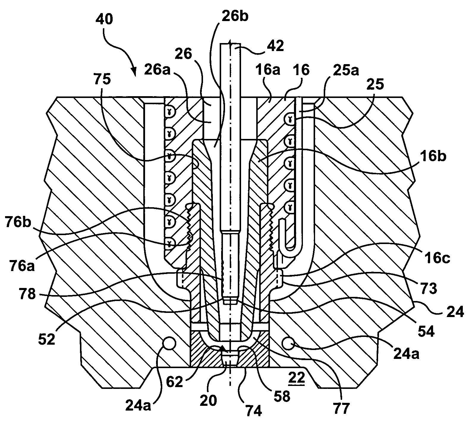
[0010]In a first aspect, the invention is directed to an injection molding apparatus comprising a manifold, a nozzle, a mold block, a valve pin, a first guidance and alignment structure, and a second guidance and alignment structure. The manifold has an inlet for receiving melt from a melt source. The manifold defines a runner that is downstream from the inlet and upstream from a manifold outlet. The nozzle defines a nozzle melt channel. The nozzle melt channel is downstream from the manifold outlet. The nozzle includes a nozzle body, a nozzle tip, a sealed piece, and a heater thermally connected to the nozzle body for heating melt in the nozzle melt channel. The nozzle tip and the seal piece are connected with respect to the nozzle body. The nozzle tip defines a portion of the nozzle melt channel. The thermal conductivity of the nozzle tip is higher than the thermal conductivity of the nozzle body. The thermal conductivity of the seal piece is lower than the thermal conductivity of the nozzle body. The mold block defines a mold cavity. The mold block defines a gate into the mold cavity. The gate is downstream from the nozzle melt channel. The gate includes a gate sealing surface. The mold block has at least one cooling channel therein for conveying a coolant therethrough for cooling the mold cavity. The mold block and the seal piece engage each other to inhibit melt leakage therebetween. A chamber is defined between the mold block, the nozzle tip, and the seal piece. The chamber is positioned downstream from the nozzle melt passage and upstream from the gate. The nozzle tip has sufficient surface area in the chamber to maintain melt in the chamber in a substantially molten state. The valve pin is movable into and out of the gate to control melt flow through the gate. The valve pin has a bottom end. The valve pin has a valve pin sealing surface proximate the bottom end. The valve pin sealing surface is engageable with the gate sealing surface to inhibit melt flow into the mold cavity. The first guidance and alignment structure is connected to the valve pin. The first guidance and alignment structure includes a first guide surface and first alignment surface. The first guide surface has a cross-sectional diameter that decreases gradually in a downstream direction. The first alignment surface is generally cylindrical. The first guide surface is positioned immediately downstream from the first alignment surface. The second guidance and alignment structure is connected to the mold block upstream from the gate. The second guidance and alignment structure includes a second guide surface and a second alignment surface. The second guide surface has a diameter that decreases gradually in a downstream direction. The second alignment surface is generally cylindrical. The second guide surface is positioned immediately upstream from the second alignment surface. The second guide surface is positioned to engage the first guide surface to slide the valve pin into alignment with the gate when the valve pin is misaligned with the gate during movement of the value pin towards the gate. The second guide surface is positioned to complete alignment of the valve pin with the gate prior to contact between the valve pin and the gate. The second alignment surface is positioned to engage the first alignment surface to maintain the valve pin in alignment with the gate during movement of the valve pin towards the gate.

Problems solved by technology

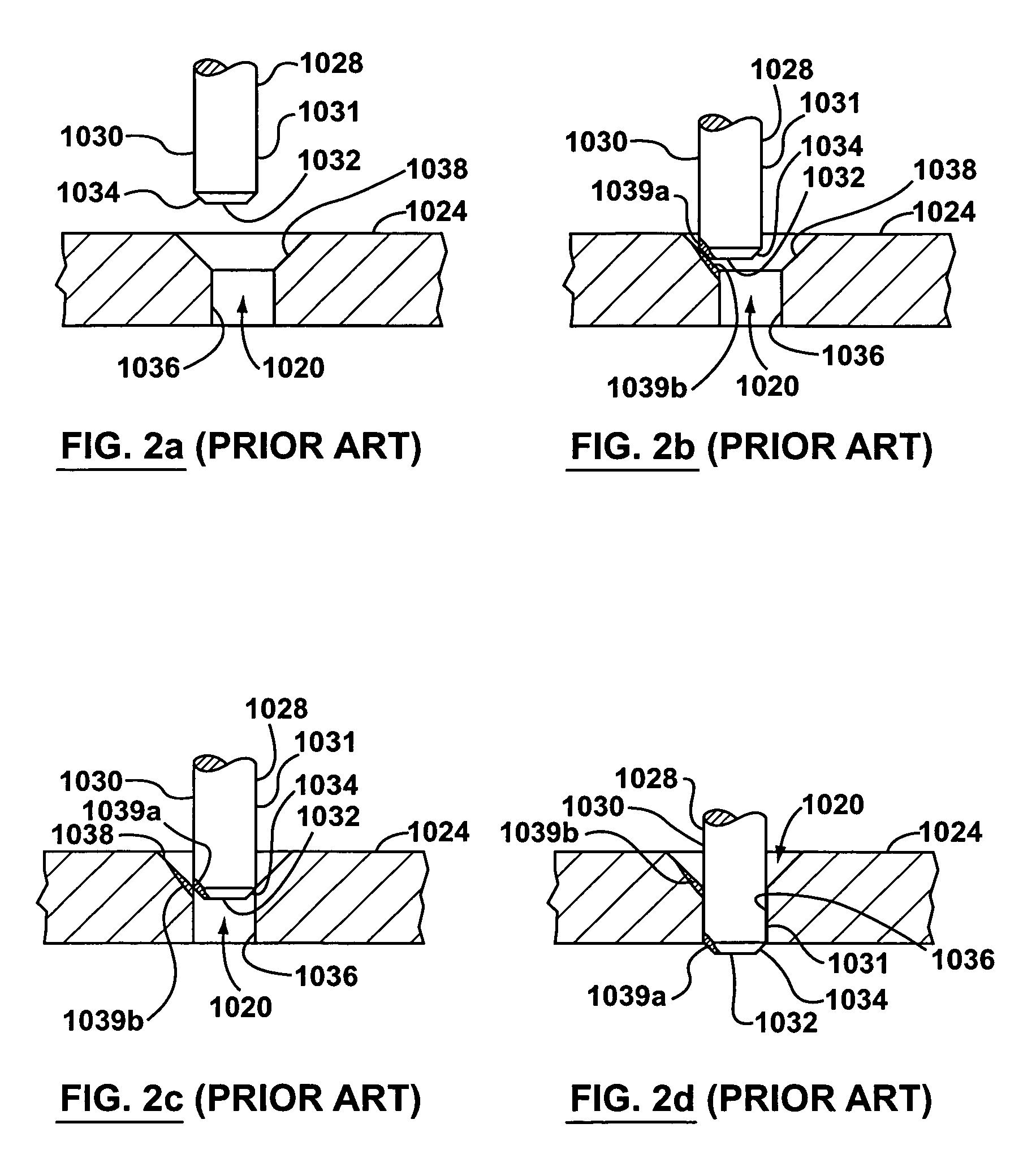
Due to a variety of reasons, however, the tip of the valve pin may be misaligned with the gate as it enters the gate.
Also, thermal expansion and contraction of the components of the injection molding apparatus, which takes place repeatedly during an injection molding campaign can cause components to shift, ultimately resulting in misalignment of the nozzle and valve pin with the gate.
Non-homogeneity in the melt itself can cause the melt to exert uneven fluid pressure on the valve pin body, which can push the sealing end of the valve pin out of alignment with the gate.
When a misaligned valve pin is moved to close a gate, the valve pin collides with the gate and can cause scoring of the sealing surfaces on the valve pin and / or the gate.
This can ultimately result in poor quality parts with blemishes around the gate, and can cause other problems with the molding operation.
Furthermore, a damaged valve pin or gate can be expensive and time consuming to replace.
The damage may happen immediately, or alternatively it may happen gradually, over many cycles of opening and closing the valve pin.
Furthermore, the presence of such guide means in the nozzle melt channel typically renders more difficult a cleanout of the nozzle melt channel, hampering for example the changeover of a machine to run a new melt.
However, because a substantial portion of the nozzle melt channel is offset from the center of the nozzle, the heat distributed to the melt flowing therethrough is uneven, which can cause difficulties in controlling melt temperature.
Other problems also exist, which originate from the manufacture of the nozzles themselves instead from the properties of the melt flow.
Manufacturing errors may exist in the nozzles, which can introduce a misalignment between the valve pin and the gate that is ‘built-in’.
The guide means that are described above, which are built into the nozzle itself, do nothing to correct this particular cause of misalignment.
Another issue relating to the valve pin has to do with the heat transfer characteristics of the nozzle and the mold plate.
In some configurations of nozzle and mold plate, the melt in the space solidifies as a result of the combined effects of cooling from the mold plate, and insufficient heat transfer from the nozzle components.
Furthermore, the solidified melt can cause wear on the leading edge of the valve pin, particularly if the melt is a glass-filled plastic or is some other abrasive material.
Thus, it is possible for the valve pin to incur wear on its leading edge and sealing surfaces even when it is in perfect alignment, depending on the thermal characteristics of the molding operation and the material being injected.

Method used


Image

  • Valve pin guidance and alignment system for an injection molding apparatus
  • Valve pin guidance and alignment system for an injection molding apparatus
  • Valve pin guidance and alignment system for an injection molding apparatus

Examples


Embodiment Construction

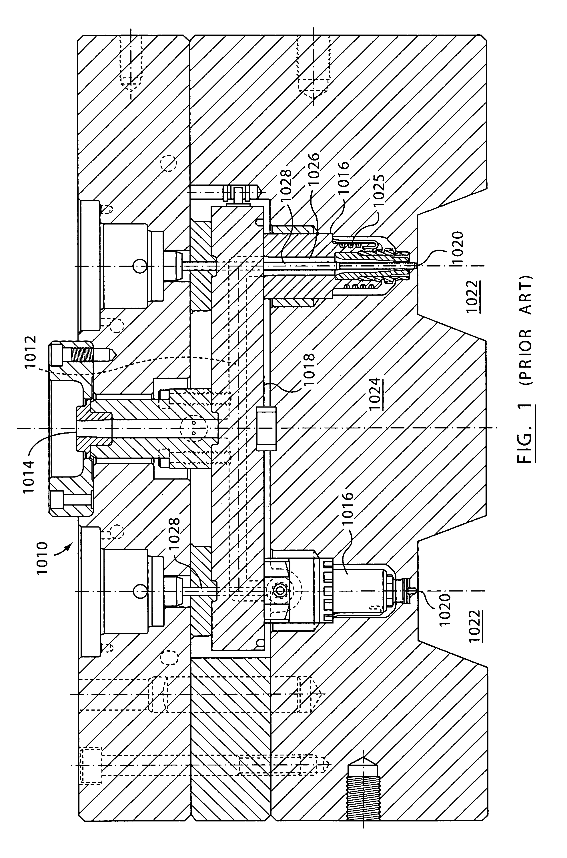
[0037]Reference is made to FIG. 1, which shows an injection molding apparatus 1010 of the prior art. The injection molding apparatus 1010 includes one or more runners 1012, that transfer melt from an inlet 1014 to one or more nozzles 1016. The runners 1012 are defined within one or more molding apparatus plates, such as, for example, a manifold 1018. The inlet 1014 is adapted to be fluidly connected to a melt source (not shown).

[0038]The nozzles 1016 transfer melt from the runners 1012 through one or more gates 1020 and into one or more mold cavities 1022 defined in a mold plate 1024. A heater 1025 may heat each nozzle 1016. Each nozzle 1016 defines a nozzle melt channel 1026 which is in fluid communication with a runner 1012 and thus, with the melt source.

[0039]A valve pin 1028 is movable within each nozzle melt channel 1026 to open and close one of the gates 1020, permitting or restricting the flow of melt into the mold cavity 1022. The configuration of the end portion of the valv...


PUM

PropertyMeasurementUnit
surface areaaaaaaaaaaa
cross-sectional diameteraaaaaaaaaa
diameteraaaaaaaaaa

Abstract

An injection molding apparatus includes a nozzle body, a valve pin, a nozzle tip, a seal piece, and a mold gate insert. The nozzle body has a melt channel. The valve pin is at least partially positioned in the melt channel. The valve pin has a first guidance and alignment structure thereon. The nozzle tip is connected to the nozzle body. The seal piece is connected to the nozzle body. The mold gate insert defines a gate and is in contact with the seal piece. The nozzle tip has a higher thermal conductivity than the nozzle body. The seal piece has a lower thermal conductivity than the nozzle body. The mold gate insert has a higher thermal conductivity than the seal piece. The mold gate insert includes a second guidance and alignment structure thereon that contacts the first guidance and alignment structure before the valve pin contacts the gate.

Description

FIELD OF THE INVENTION[0001]This invention relates to an injection molding apparatus, and more particularly to a valve pin guidance and alignment system for a valve pin on an injection molding apparatus.BACKGROUND OF THE INVENTION[0002]It is known for a nozzle in hot runner injection molding apparatuses to include a valve pin gating mechanism at each gate into each mold cavity. The valve pin is typically moved in a melt channel of the nozzle towards or away from the gate, to control the flow of melt into the melt cavity. In order to provide a good seal at the gate, both the tip portion of the valve pin and the corresponding sealing surface on the gate must typically be machined to very close tolerances[0003]Due to a variety of reasons, however, the tip of the valve pin may be misaligned with the gate as it enters the gate. For example, the nozzle in which the valve pin moves may be misaligned with the gate. Also, thermal expansion and contraction of the components of the injection m...

Claims


Application Information

Patent Timeline
Patent Type & Authority Patents(United States)
IPC IPC(8): B29C45/23B29C45/27B29C45/28
CPCB29C45/2806B29C45/278B29C45/2711B29C45/2701
Inventor FISCHER, JONATHONBABIN, DENIS
Owner MOLD MASTERS 2007
Learn More