Inductively heated clothing

a technology of inductive heating and clothing, applied in the field of clothing items, can solve the problems of difficult laundering, difficult positioning of heating packs, and bulky batteries, and achieve the effect of improving resistance-heated clothing items and battery-powered

Inactive Publication Date: 2008-08-21
TSI TECH
View PDF22 Cites 124 Cited by
  • Summary
  • Abstract
  • Description
  • Claims
  • Application Information

AI Technical Summary

Benefits of technology

[0013]In another embodiment, a battery powered, resistance-heated clothing item may be improved by providing an inductively powered battery charging assembly with the clothing item. Such a charging assembly includes an induction coil operably coupled with the battery and operable to generate a charging current when subjected to an alternating magnetic field.

Problems solved by technology

Such systems can be a problem because the circuit wiring may be broken during extended use and can be difficult to launder.
Moreover, the batteries tend to be bulky and are often placed in awkward positions, such as on the wrist for heated gloves.
These heating packs do not perform well where airflow is restricted, such as in footwear applications.
Further, these packs are designed for single use only, which significantly increases costs and creates waste disposal problems.
This system does not permit reheating while the footwear is worn, and requires long warming times owing to restricted heat transfer over small surface areas.
All of these systems suffer from the problems of excess weight, lack of durability and cleanability issues.
Again, this type of heating is deficient in that the heating elements are of single use design and must be periodically replaced by the user.

Method used


Image

  • Inductively heated clothing
  • Inductively heated clothing
  • Inductively heated clothing

Examples


Embodiment Construction

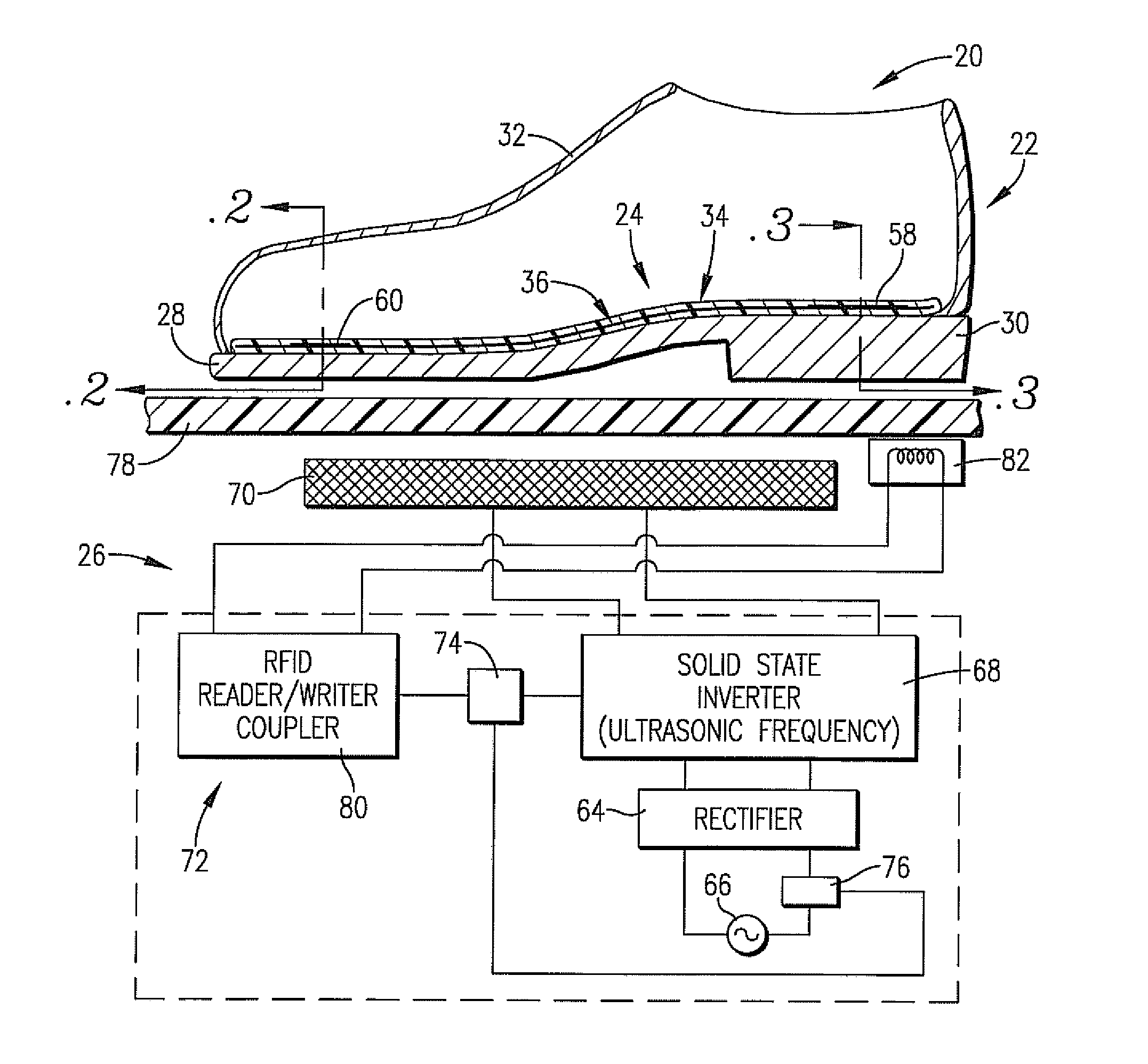
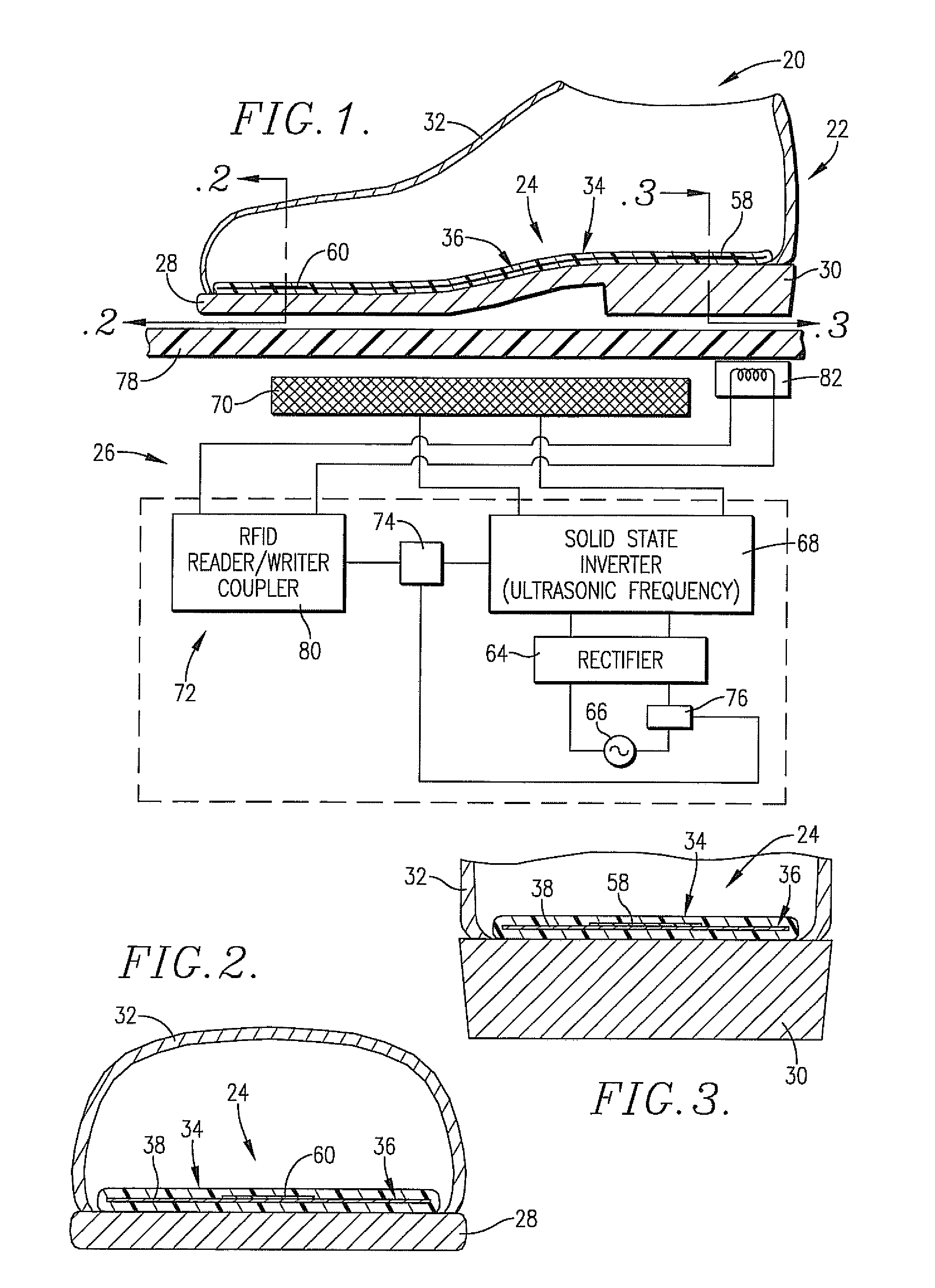
[0028]Turning now to the drawings, an induction footwear assembly 20 is illustrated in FIGS. 1, 1A, 2, and 3 and broadly includes a shoe 22 equipped with an induction heatable insole insert 24, as well as an induction heater 26. As shown, the shoe 22 is positioned atop heater 26 in an orientation for induction heating of the insert 24 as will be described.

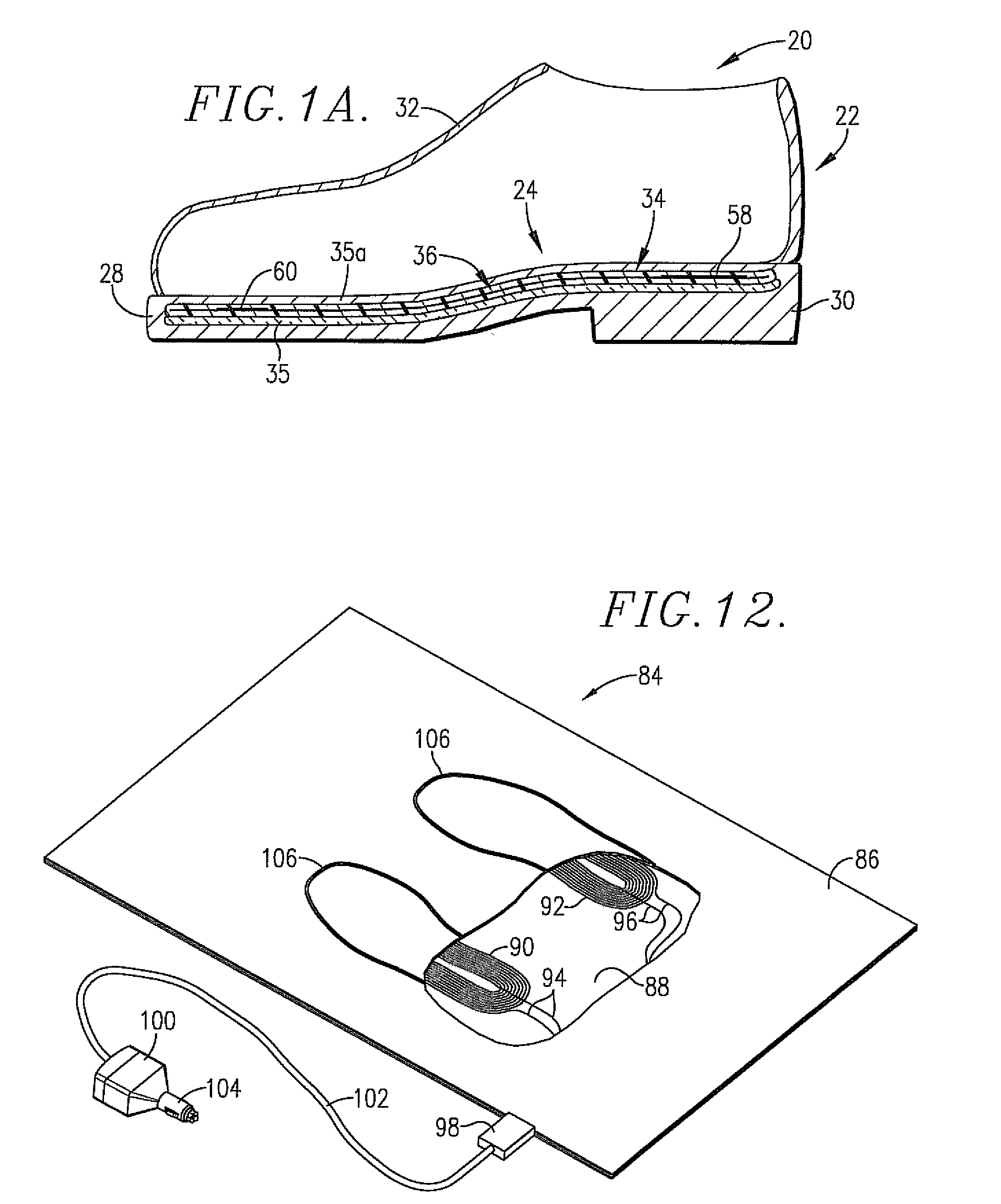
[0029]The shoe 22 in FIG. 1 is itself entirely conventional and includes a sole 28, heel 30, and upper 32. An insert 24 is placed within the shoe and can be removed. The shoe 22 in FIG. 1A uses conventional construction but has the insert 24 molded into the sole 28 and / or heel 30. A layer of thermal insulation 35 such as aerogel manufactured by companies such as Aspen Aerogel is provided below the insert 24. The insert 24 is fully encapsulated in the sole 28 and / or heel 30 by a layer 35a. Alternatively, the top of insert 24 may be covered by a separate cover layer 35a which is formed of polymer-based materials, leather, or other ma...


PUM


Abstract

Induction heatable clothing items such as footwear (22) and apparel (160) are provided which include a clothing body having an induction heatable element (36, 108, 112, 114, 116) and preferably having heat retentive material containing phase change material, wherein the element (36, 108, 112, 114, 116) is operable to be heated when subjected to an alternating magnetic field. The clothing items (22, 160) are heated using induction heaters (26, 84). In preferred forms, wireless temperature sensing is used to control heating of the items (22, 160). To this end, the heating elements (36, 108, 112, 114, 116) may be provided with RFID tag / temperature sensor assemblies (58, 60, 110), and the induction heaters (26, 84) are equipped with correlated RFID reader / writer devices (80). Alternately, microwire temperature sensors (120) may be used with the induction heaters (26, 84) having microwire detectors. In other embodiments, temperature monitoring is achieved using impedance detection feedback control.

Description

CROSS REFERENCE TO RELATED APPLICATIONS[0001]This application claims the benefit of Application Ser. No. 60 / 901,703, filed Feb. 16, 2007, and this application is incorporated by reference herein in its entirety.BACKGROUND OF THE INVENTION[0002]1. Field of the Invention[0003]The present invention is broadly concerned with clothing items such as footwear and apparel which can be inductively heated for cold weather use. More particularly, the invention is concerned with such clothing items and methods of use thereof wherein the items include an induction heatable element which is heated when subjected to an alternating magnetic field. The invention also pertains to assemblies including such heatable clothing along with an induction heater designed to heat the elements of the clothing. In preferred forms, the clothing items include a device serving to limit the maximum temperature of the heatable elements, and closed loop, wireless temperature feedback allowing temperature control and m...

Claims


Application Information

Patent Timeline
Patent Type & Authority Applications(United States)
IPC IPC(8): H05B6/10H05B1/00H05B6/02A41D1/00
CPCA43B7/025A43B3/355
Inventor BOURKE, MICHAEL J.CLOTHIER, BRIAN L.
Owner TSI TECH
Why Eureka
Try Eureka