Induction heater

a technology of induction heater and heater body, which is applied in the direction of electric/magnetic/electromagnetic heating, sustainable building, coil arrangement, etc., can solve the problems of noise interference with peripheral equipment, conduction loss, and deformation of the heating surface, so as to suppress the leaked magnetic field and prevent the effect of conduction loss

Inactive Publication Date: 2016-01-28
PANASONIC INTELLECTUAL PROPERTY MANAGEMENT CO LTD
View PDF4 Cites 27 Cited by
  • Summary
  • Abstract
  • Description
  • Claims
  • Application Information

AI Technical Summary

Benefits of technology

[0028]In this way, the induction heater equipped with the plurality of heating coils and the inverters of the number less than that of heating coils can inductively heat

Problems solved by technology

Accordingly, a conduction loss occurs in the heating coil on which no heating target is placed, and thus heating efficiency may degrade.
Noise interference with peripheral equipment may also occur due to a leaked magnetic field.
Naturally, the inverters of the same number as th

Method used


Image

  • Induction heater
  • Induction heater
  • Induction heater

Examples


first exemplary embodiment

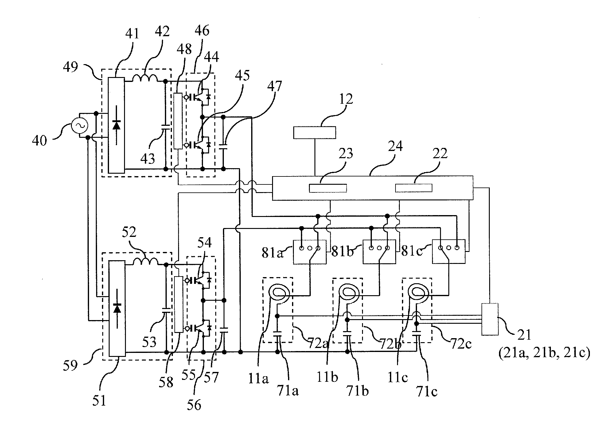
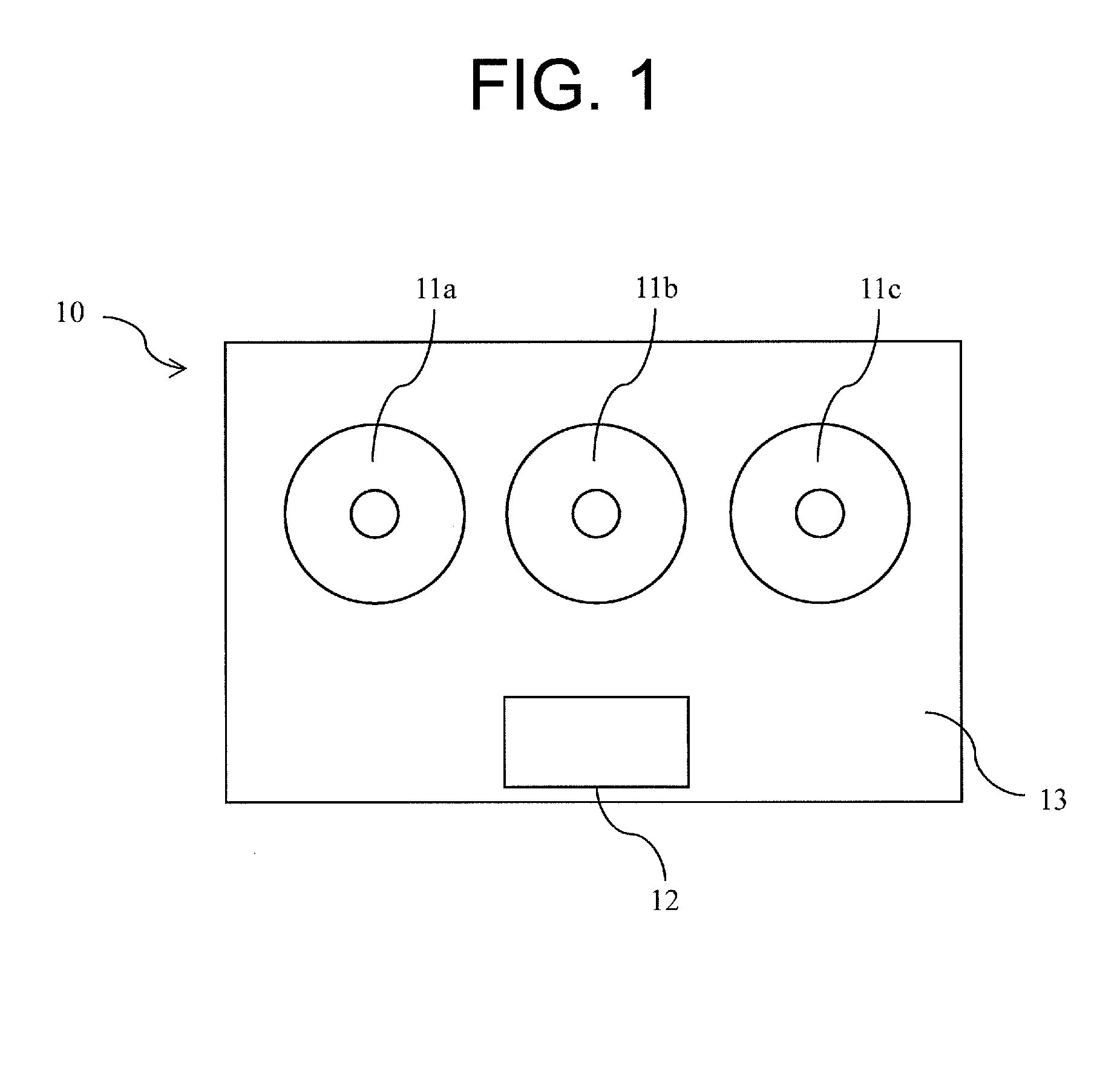
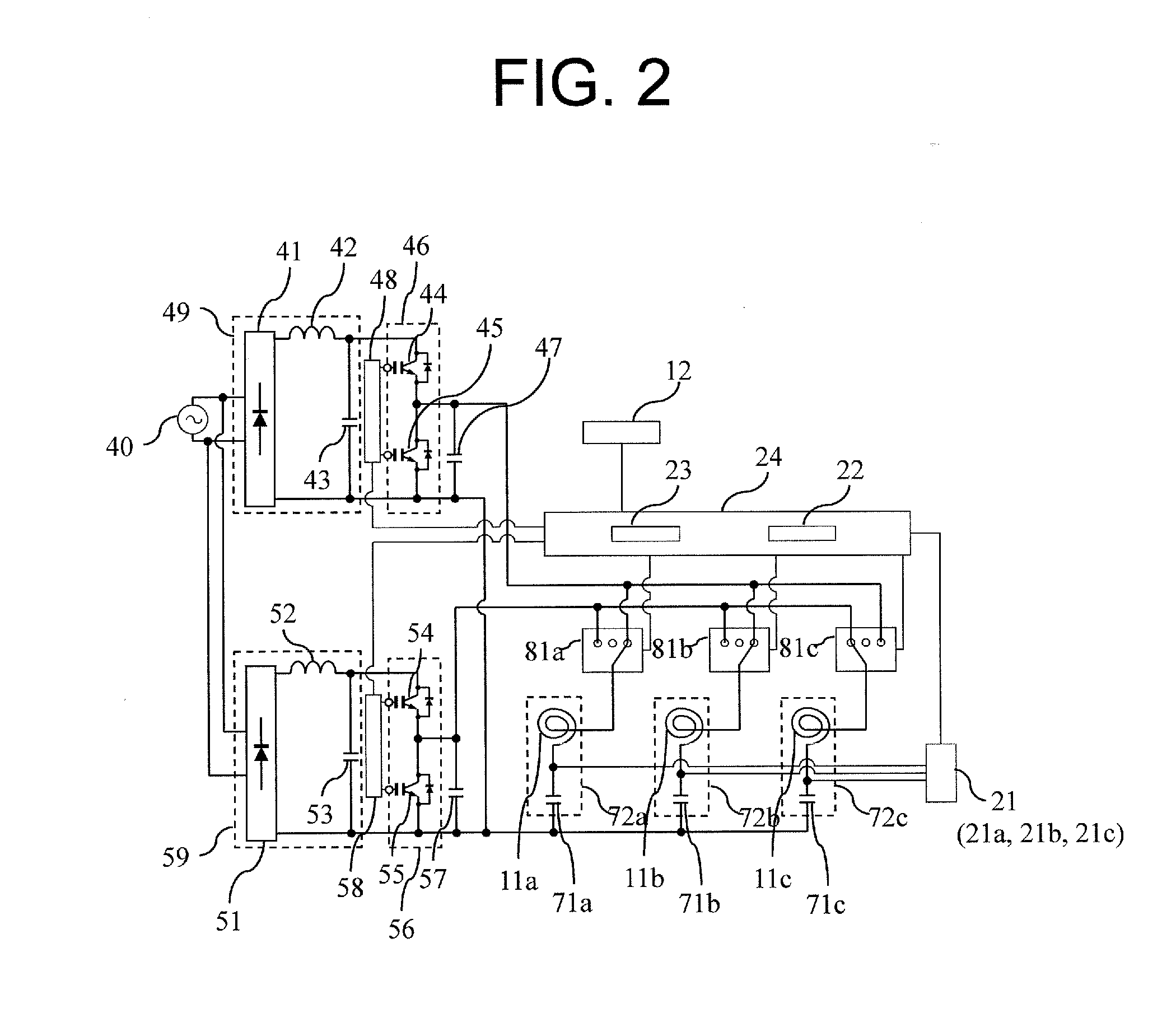
[0068]FIG. 1 is a schematic top view of an induction heater in the first exemplary embodiment. FIG. 2 is a circuit block diagram of the induction heater in the exemplary embodiment.

[0069]Components and circuit configuration of induction heater 10 in the exemplary embodiment are detailed below with reference to FIGS. 1 and 2.

[0070]Induction heater 10 in the first exemplary embodiment includes flat cooktop 13 on its top face. Cooktop 13 is configured with an electric insulating material, such as glass and ceramic, for placing a heating target, such as a pan.

[0071]Induction heater 10 includes DC power source 49 having diode bridge 41, choke coil 42, and smoothing capacitor 43, and DC power source 59 having diode bridge 51, choke coil 52, and smoothing capacitor 53 for rectifying and smoothing the power from commercial AC power source 40.

[0072]A negative bus bar of DC power source 59 is connected to a negative bus bar of DC power source 49, and has a potential same as that of the negati...

second exemplary embodiment

[0121]An induction heater in the second exemplary embodiment of the present invention is described below.

[0122]FIG. 5 shows the state that heating target 92 wider than heating target 91 is placed across heating coils 11a and 11b of induction heater 10 shown in FIG. 1.

[0123]Also in this case, same as the case in the first exemplary embodiment, inverter 46 starts to supply the container detecting current to resonance circuits 72a and 72b and inverter 56 to resonance circuit 72c according to the initial state of switching circuits 81a to 81c shown in FIG. 2.

[0124]When single heating target 92 is placed on heating coils 11a and 11b in the initial state of switching circuits 81a to 81c shown in FIG. 2, sensor 21a detects current of resonance circuit 72a and voltage of resonance capacitor 71a corresponding to the container detecting current supplied from inverter 46. Container detection unit 22 determines that heating target 91 is placed on heating coil 11a based on the output from sensor...

third exemplary embodiment

[0146]An induction heater in the third exemplary embodiment of the present invention is described below.

[0147]The operation of induction heater 10 is described when another heating target 93 is placed on heating coil 11 b in the state shown in FIGS. 3 and 4.

[0148]FIG. 7 shows the state that another heating target 91 is placed on heating coil 11b of induction heater 10 shown in FIG. 3.

[0149]When another heating target 93 is placed on heating coil 11b in the state of switching circuits 81a to 81c shown in FIG. 4, sensor 21b detects current of resonance circuit 72b corresponding to the container detecting current supplied from inverter 56 and voltage of resonance capacitor 71b. Container detection unit 22 then determines that a heating target is also placed on heating coil 11b based on an output of sensor 21b.

[0150]At the same time, since heating target 91 is already placed on heating coil 11a, container detection unit 22 recognizes that the heating target placed on heating coil 11b i...


PUM


Abstract

An induction heater includes a plurality of heating coils, a plurality of inverters, a plurality of switching circuits, command unit, sensor group, and container detection unit. The number of inverters supplying a high-frequency current to the heating coils is less than the number of heating coils. Each of the switching circuits switches an electric path of each of the heating coils such that each heating coil is connected or not connected to any of the inverters. The command unit controls driving of the inverters and switching of the switching circuits. Each sensor in the sensor group detects a response of a resonance circuit including the heating coil relative to power supply from the inverters. The container detection unit detects whether or not heating target is placed on the heating coil based on an output of the sensor. This enables to retain safety and reduce cost of the induction heater equipped with the plurality of heating coils.

Description

TECHNICAL FIELD[0001]The present invention relates to an induction heater, and more particularly to an induction heat cooking device that inductively heats a heating target, such as a cooking container, placed on a cooktop.BACKGROUND ART[0002]In the induction heat cooking device, a method of controlling two heating coils with different resonance frequencies connected to a single inverter by adjusting a frequency of a high-frequency current supplied from the inverter is disclosed (e.g., PTL 1).[0003]This method eliminates the need of inverters of the same number as that of heating coils, and thus the device cost can be reduced.[0004]However, since a plurality of heating coils are connected to a single inverter, the high-frequency current for induction heat is constantly supplied to a heating coil on which no heating target is placed during induction heating.[0005]Accordingly, a conduction loss occurs in the heating coil on which no heating target is placed, and thus heating efficienc...

Claims


Application Information

Patent Timeline
IPC IPC(8): H05B6/06H05B6/12H05B6/44
CPCH05B6/065H05B2213/07H05B6/44H05B6/1209H05B6/1272H05B2213/05Y02B40/00
Inventor KUROSE, YOICHIKITAIZUMI, TAKESHI
Owner PANASONIC INTELLECTUAL PROPERTY MANAGEMENT CO LTD
Why Eureka
Try Eureka