Temperature sensing and heating device

a temperature sensing and heating device technology, applied in the direction of electric heating, electric/magnetic/electromagnetic heating, electrical apparatus, etc., can solve the problems of water baths posing a risk of contamination of samples being heated, system limited to the maximum temperature of the sample, and existing methods of heating samples can be slow (time to heat samples) and uncontrollabl

Active Publication Date: 2014-01-09
BLUECHIIP LTD
View PDF1 Cites 28 Cited by
  • Summary
  • Abstract
  • Description
  • Claims
  • Application Information

AI Technical Summary

Benefits of technology

[0034]In one or more embodiments, the method further includes the step of applying an excitation signal to the tag to cause vibration of the resonant members by a Lorentz-type force.
[0035]In one or more embodiments, an induction heater heats the substance, the induction heater including an induction coil forming part of a tank circuit; a control circuit for supplying AC current to the tank circuit; and tuning circuitry, including frequency determining circuitry, to match the frequency of AC current to the resonant frequency of the tank circuit. In this case, the method may further include the step of the frequency determining circuitry determining the resonant frequency of the tank circuit and frequency modulation circuitry to adjust the frequency of the AC current to the resonant frequency of the tank circuit.
[0036]In one or more embodiments, the method may further include the step of the heater controller controlling operation of the induction heater to heat the substance, in response to an input substance temperature set-point.
[0037]In one or more embodiments, the method may further include the step of the heater controller controlling operation of the induction heater to heat the substance, in response to an input substance temperature heating rate.

Problems solved by technology

These systems are limited to the maximum temperature of the sample that can be achieved.
Existing methods of heating samples can be slow (time to heat sample) and uncontrollable.
In addition, water baths pose a risk of contamination to samples being heated and between samples, and while the bath temperature can be monitored, individual vial or tuba sample temperature cannot be monitored.
Such vial heating systems provide inaccurate heating of substances stored in the vial.

Method used


Image

  • Temperature sensing and heating device
  • Temperature sensing and heating device
  • Temperature sensing and heating device

Examples


Embodiment Construction

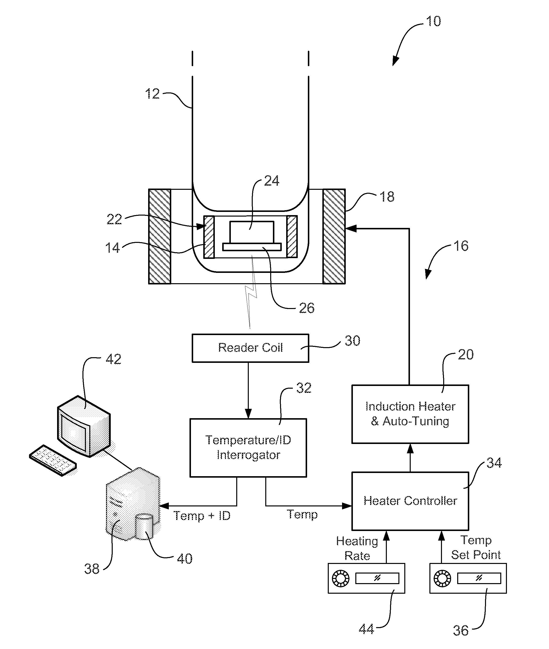
[0047]FIG. 1 depicts a system 10 for heating a substance stored in a container 12, in this case, a vial. The induction heating system 10 includes a conductive ring or like heating element 14. The heating element 14 is preferably formed from an electrically conductive and / or ferromagnetic material and may conveniently be formed from a metal or a metal alloy with a high magnetic permeability, such as steel, nickel or other ferromagnetic material. The heating element 14 is affixed to the vial 12 so as to be in thermal contact with substances stored within the vial. In the embodiment depicted in FIG. 1, the heating element 14 is formed in a wall of the vial 12.

[0048]The heating element 14 is used by the induction heating system 10 to generate heat locally via an induction heating process. In that regard, the induction heating system 10 further includes an induction heater 16 including notably an induction coil 18 and induction heater control unit 20 for supplying AC current to thereby g...


PUM


Abstract

An induction heating system including a container for storing a substance; a heating element in thermal contact with the substance; a machine readable tag in thermal contact with the substance, the tag having a machine readable temperature-dependant characteristic; an interrogator for reading the temperature-dependant characteristic of the tag and for determining the current temperature of the substance; an induction heater for generating an AC magnetic field to heat the heating element; and a heater controller for controlling operation of the induction heater, in response to the substance temperature determined by the interrogator, to heat the substance.

Description

FIELD OF THE INVENTION[0001]The present invention relates to the heating of substances stored in containers. The Invention is suitable for use in heating chemical assay samples, stem cell samples and other biological samples in vials or test tubes, and it will be convenient to describe the invention in relation to that exemplary application. It is to be appreciated however, that the invention may be, used in a wide variety of applications in which substances stored in containers are required to be heated.BACKGROUND OF THE INVENTION[0002]Biological samples are collected and stored in many different types of facilities for a great variety of applications. Such applications include the storage of samples collected during clinical trials in pharmaceutical companies, research samples used in university laboratories, samples archived in hospitals, samples used in the discovery of biological marks for diagnostic testing, forensic samples from crime or disaster scenes and so on.[0003]Vials ...

Claims


Application Information

Patent Timeline
Patent Type & Authority Applications(United States)
IPC IPC(8): H05B6/06
CPCH05B6/06H05B2213/07
Inventor CHAFFEY, JASON PHILLIPMILJANIC, MIROSLAV
Owner BLUECHIIP LTD
Why Eureka
Try Eureka