
Bidirectional Battery Charge Controller

Active Publication Date: 2008-08-21
TOWER SEMICONDUCTOR
View PDF19 Cites 65 Cited by
  • Summary
  • Abstract
  • Description
  • Claims
  • Application Information

AI Technical Summary

Benefits of technology

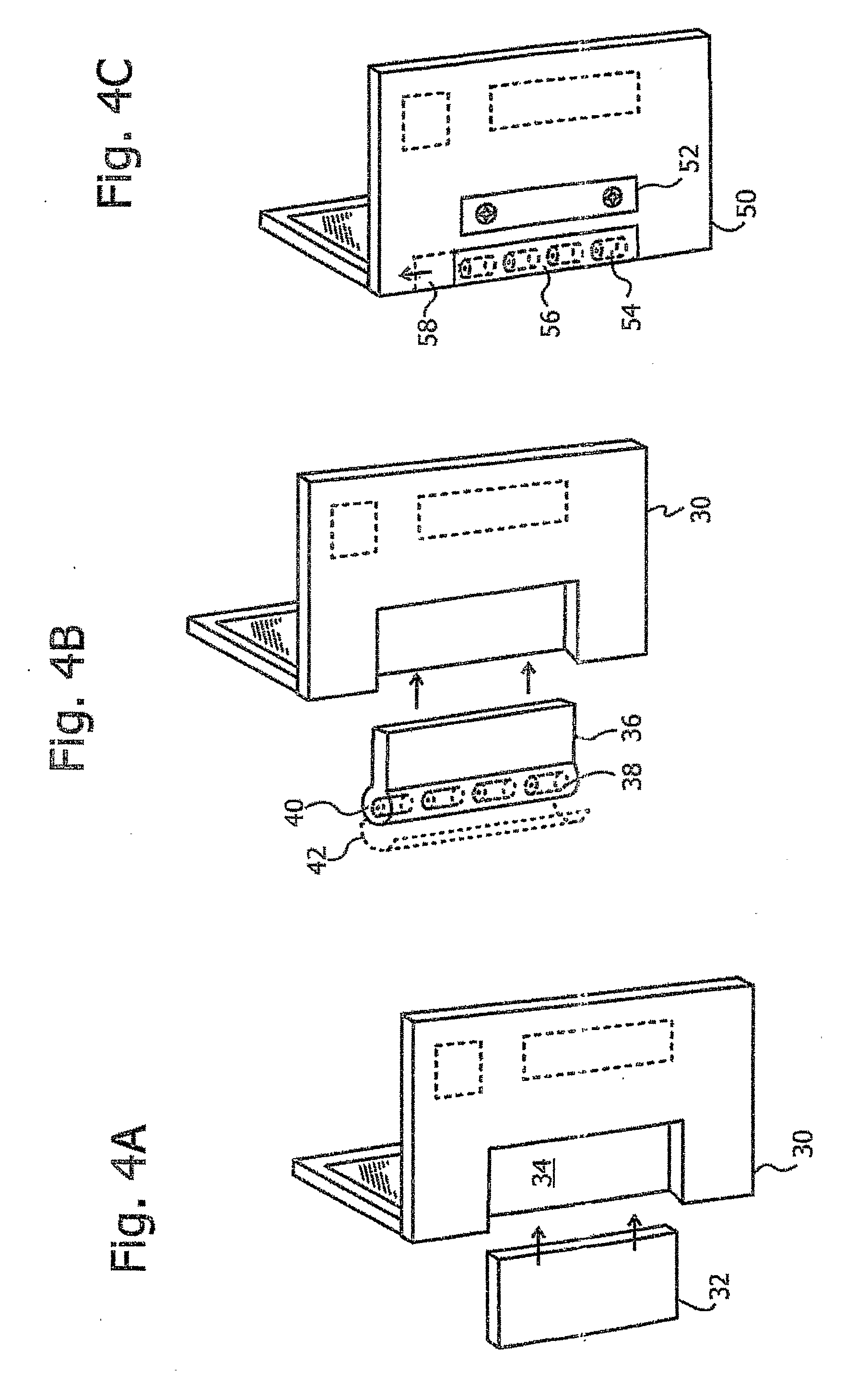
[0011]In cases where the auxiliary battery is rechargeable, the bidirectional charge controller enables the auxiliary battery and main device rechargeable battery to operate essentially transparently in relation to each other, such that they can be considered to behave as one large rechargeable battery. The auxiliary battery in this case thus effectively adds capacity to the main rechargeable battery. This enables the auxiliary battery pack to be considered as the only replaceable part of the total battery capacity of the device, and also enables the main battery to be permanently wired into the device, if desired, thus saving the costs and the potentially reduced reliability of battery contacts. Furthermore, when a rechargeable auxiliary battery is used, the device's power management system can be arranged to use the capacity of this battery first, and only if it is depleted, to use the main battery of the device. The life of the main rechargeable battery is thus lengthened, since there is less total use of it. According to this arrangement, the device may advantageously be constructed such that the only battery in the device which is meant to be readily user-replaceable is the auxiliary battery, which can then preferably be housed in its own compartment, separately from the main battery which the user need generally not be concerned with.
[0024]There is even further provided in accordance with a preferred embodiment of the present invention, a battery power supply system as described hereinabove, and wherein the additional battery comprises at least one rechargeable cell, and the bidirectional charge controller preferentially draws current from the additional battery before drawing current from the rechargeable battery. In such an embodiment, the preferential drawing of current from the additional battery before the rechargeable battery is then operative to lengthen the lifetime of the rechargeable battery. Furthermore, the main rechargeable battery is then preferably used only after the additional battery is substantially depleted, such that the life of the main rechargeable battery is lengthened.

Problems solved by technology

Unfortunately, the inclusion of these features usually places additional demands on the rechargeable batteries that power the cell phones.
The net result is that cell phone run times are becoming shorter due to the increased power demands.
The combination of these two trends, i.e. increased electrical demand and reduced battery size, often causes cell phone users to experience a lost telephone call or data transmission due to the depletion of the phone battery at an inopportune moment.
An additional trend that complicates resolution of this problem is that most cell phones require a battery that has specific size and shape characteristics.
Furthermore, the recharging port built into the cell phones limit the type of charger that can be connected to the cell phone.
Collectively, these factors limit the consumer's ability to readily replace the depleted battery with another power source.
Consequently, when the battery is depleted, the entire battery pack, including the plug, must be discarded, increasing consumer costs.
Additionally, rechargeable batteries built into portable electronic devices are generally expensive and not widely available.
Replacement of such originally equipped batteries with lower cost or more readily available types of batteries generally results in degradation of the available power for the device, or of the use-time of the device, since the built-in batteries supplied by the device manufacturer have usually been selected for optimum performance and operating time.
This is particularly true of lap-top and other portable computers, where the critical nature of the tasks performed generally negates compromise in built-in battery selection and use.
Therefore, there have been few previous attempts at providing cheaper or more versatile battery power solutions for such portable electronic devices.

Method used


Image

  • Bidirectional Battery Charge Controller
  • Bidirectional Battery Charge Controller
  • Bidirectional Battery Charge Controller

Examples


Embodiment Construction

[0038]The bidirectional battery system of the present invention is directed at providing an auxiliary battery for portable electronic devices, such as cellular telephones, video cameras, laptop computers, and the like, which provides readily available and versatile power to augment the main rechargeable battery in the device, and which can include different types of cells for use in a back-up power function.

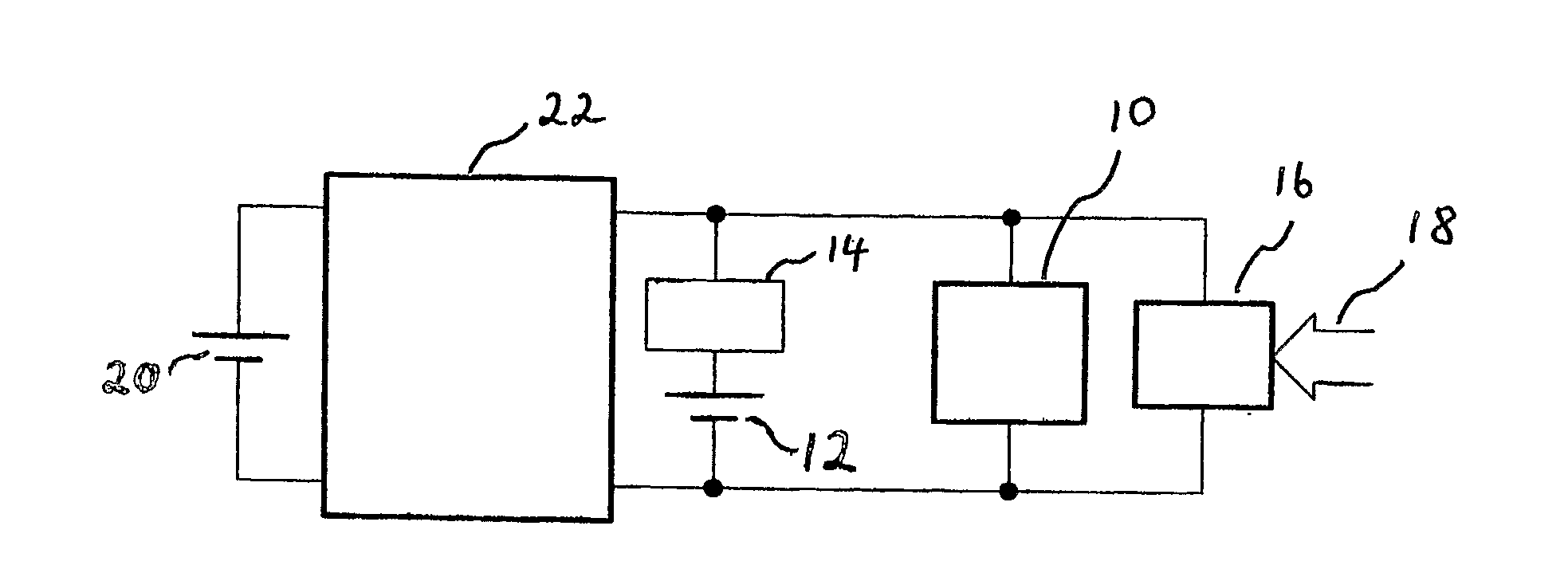
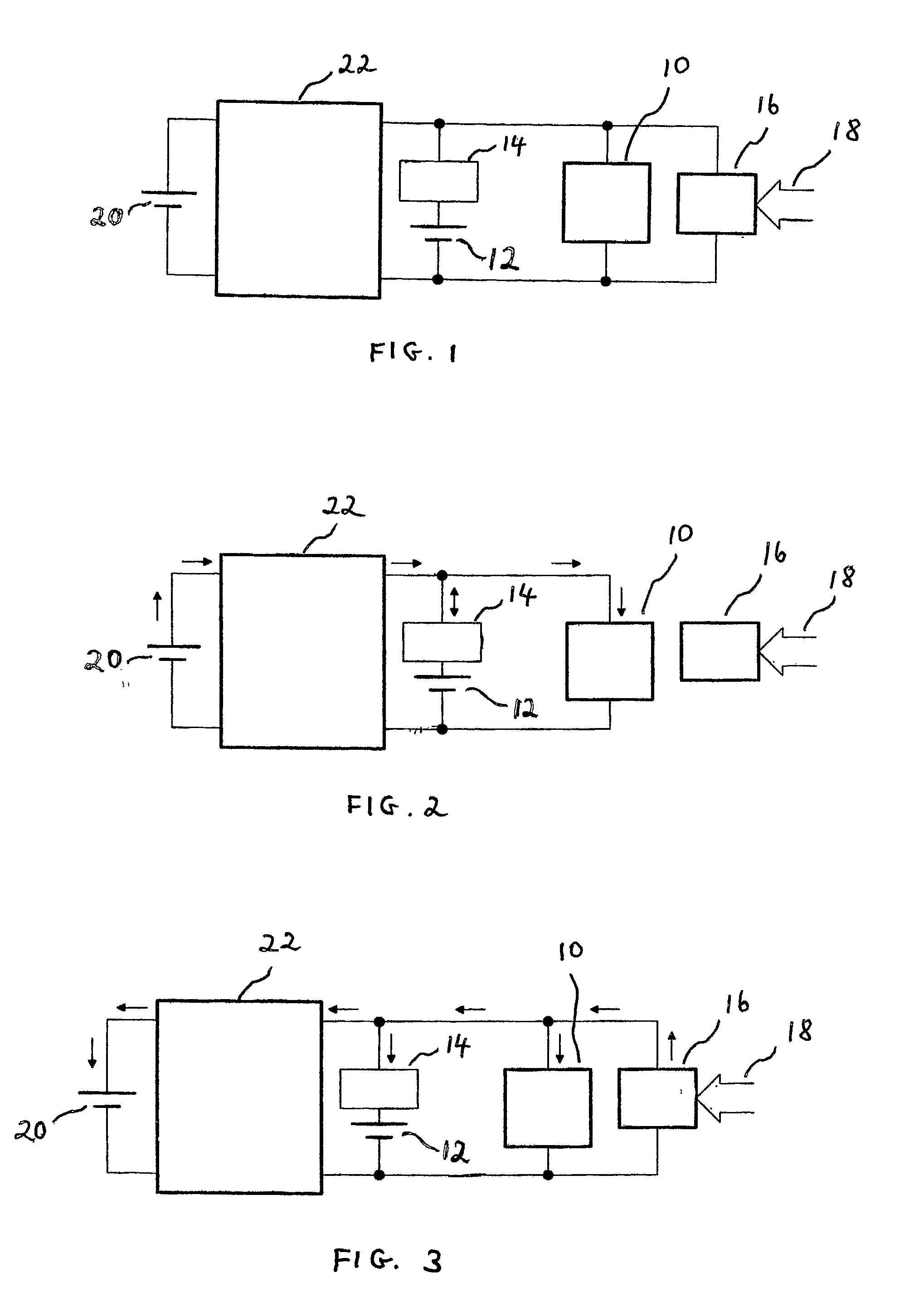
[0039]Reference is now made to FIG. 1 which illustrates the overall arrangement of a bidirectional battery system constructed and operative according to a preferred embodiment of the present invention. The operating circuitry of the portable device 10 is powered in the usual manner by its own built-in rechargeable battery 12, which can preferably be a Li-ion type of battery. An internal protection circuit 14 protects the built-in rechargeable battery against harmful conditions, including overcharge, over-discharge and excessive temperature. In addition, an auxiliary or additional...


PUM


Abstract

A bidirectional battery charge control system for a portable electronic device which uses a rechargeable main battery. The system enables the connection of an auxiliary battery to the device for inputting additional current to the device. Control of the current flow into and out of the auxiliary battery is performed by a bidirectional charger. The auxiliary battery can contain one or more readily available primary or secondary cells, and the bidirectional charger is such that an external charger connected to the device, generally used to charge the main rechargeable battery of the device, can also recharge a secondary cell or cells in the auxiliary battery, if such are installed. The use of such an auxiliary battery enables the main battery to be hard-wired into the device.

Description

FIELD OF THE INVENTION[0001]The present invention relates to the field of battery equipped power supply systems for use in handheld electronic devices, and especially controllers for the bidirectional regulation of the charging and discharging of auxiliary batteriesBACKGROUND OF THE INVENTION[0002]The proliferation of portable battery powered devices, such as cellular telephones, video cameras, portable laptop computers, and the like, has increased dramatically in the last several years and this trend is expected to continue. These devices typically use a rechargeable battery that is built into the device to provide the needed power. The length of time that the battery powers the device is dependent primarily upon the size of the battery and the number of energy consuming features built into the device. For instance, in response to consumer demand, cell phone manufacturers often incorporate into the phones features such as the ability to send and receive digital pictures and / or text...

Claims


Application Information

Patent Timeline
IPC IPC(8): H02J7/00
CPCH02J7/0054H02J7/342Y02E60/10H02J7/0024H01M10/441H01M10/48H01M10/0525H01M2250/30
Inventor MANOR, DRORWEINSTEIN, GUY
Owner TOWER SEMICONDUCTOR
Learn More