
Nearly Collision-Free Channel Access System and Method

a channel access system and collision-free technology, applied in the field of adhoc wireless communication networks, can solve problems such as collision-free transmissions, and achieve the effect of reducing the concentration between different nodes

Inactive Publication Date: 2008-08-21
STINGRAY IP SOLUTIONS LLC
View PDF19 Cites 43 Cited by
  • Summary
  • Abstract
  • Description
  • Claims
  • Application Information

AI Technical Summary

Benefits of technology

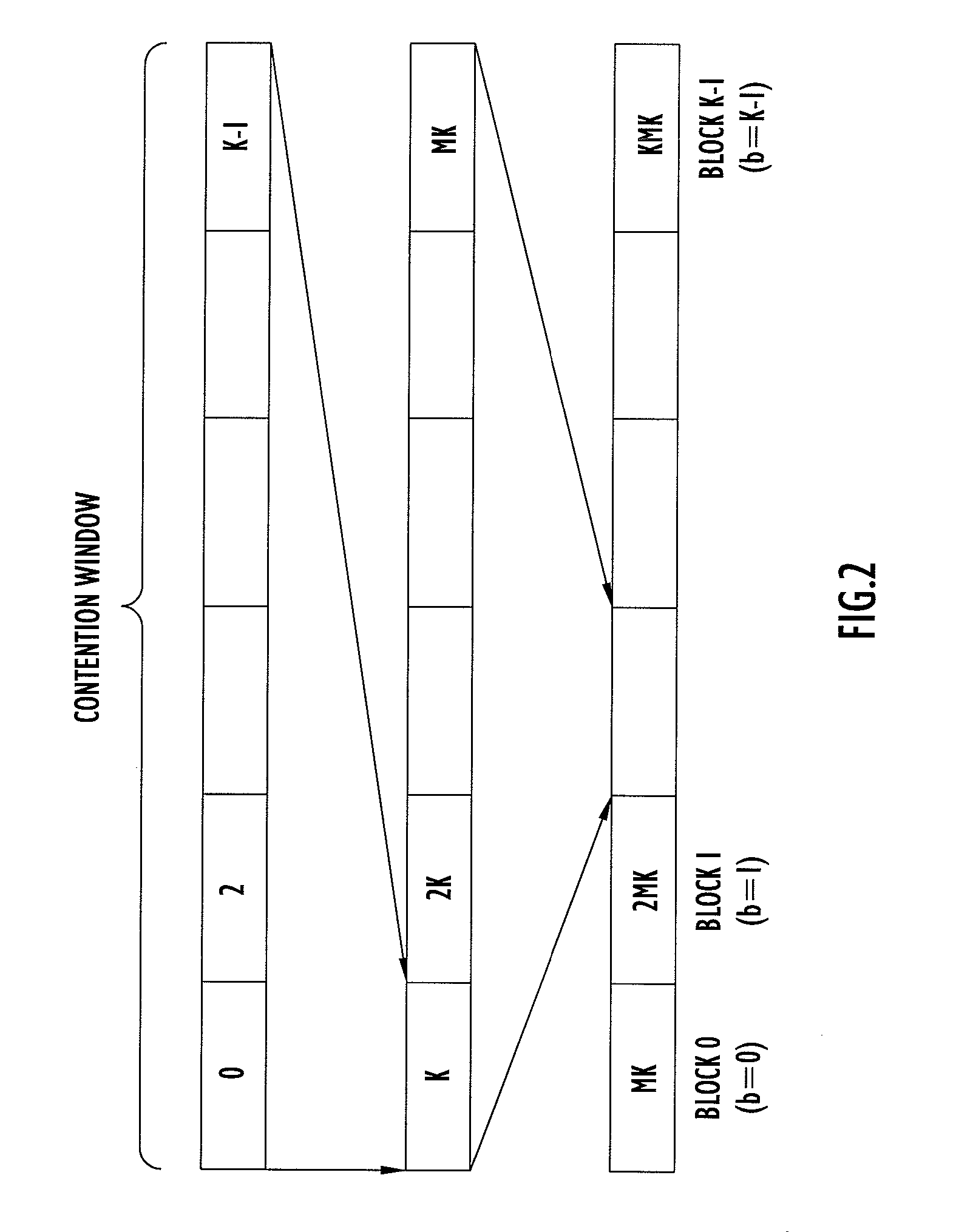
[0014]Briefly, the present invention is directed to controlling access to a communication channel for each of a plurality of nodes in a wireless ad hoc communication network. According to one embodiment, each node uses a predetermined rule, such as a hash function, to compute which of a plurality of time slots during a contention window it is to attempt transmissions. Each node in the network follows the same rule to access the channel and as a result no additional overhead transmissions are required between the nodes. In addition, contention among different nodes is reduced when a node needs to repeat an attempt to make a transmission. When a node has data to transmit on the channel, it determines a time slot in the contention window period during which to attempt the transmission using a computation that is based on a number identifier assigned to the node, the number of time slots in the contention window period and a transmission count value that represents the number of attempts the node has made to make the transmission. Under most conditions, this scheme leads to collision-free transmissions.

Problems solved by technology

Under most conditions, this scheme leads to collision-free transmissions.

Method used


Image

  • Nearly Collision-Free Channel Access System and Method
  • Nearly Collision-Free Channel Access System and Method
  • Nearly Collision-Free Channel Access System and Method

Examples


Embodiment Construction

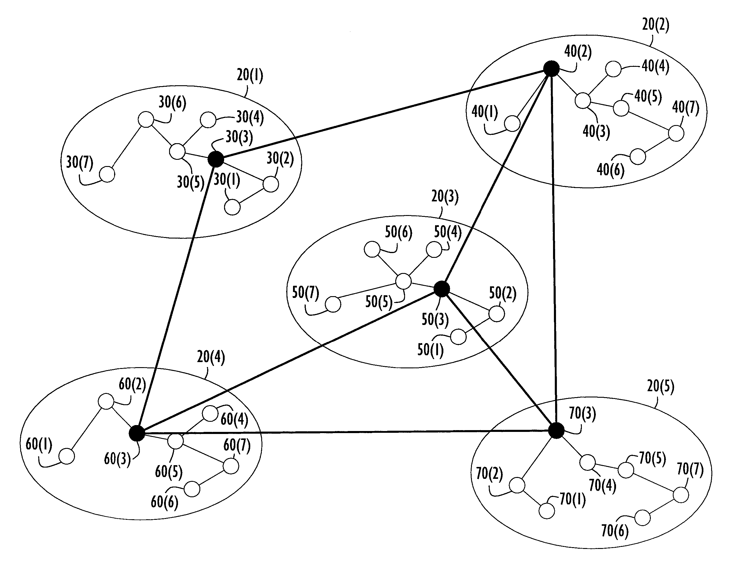
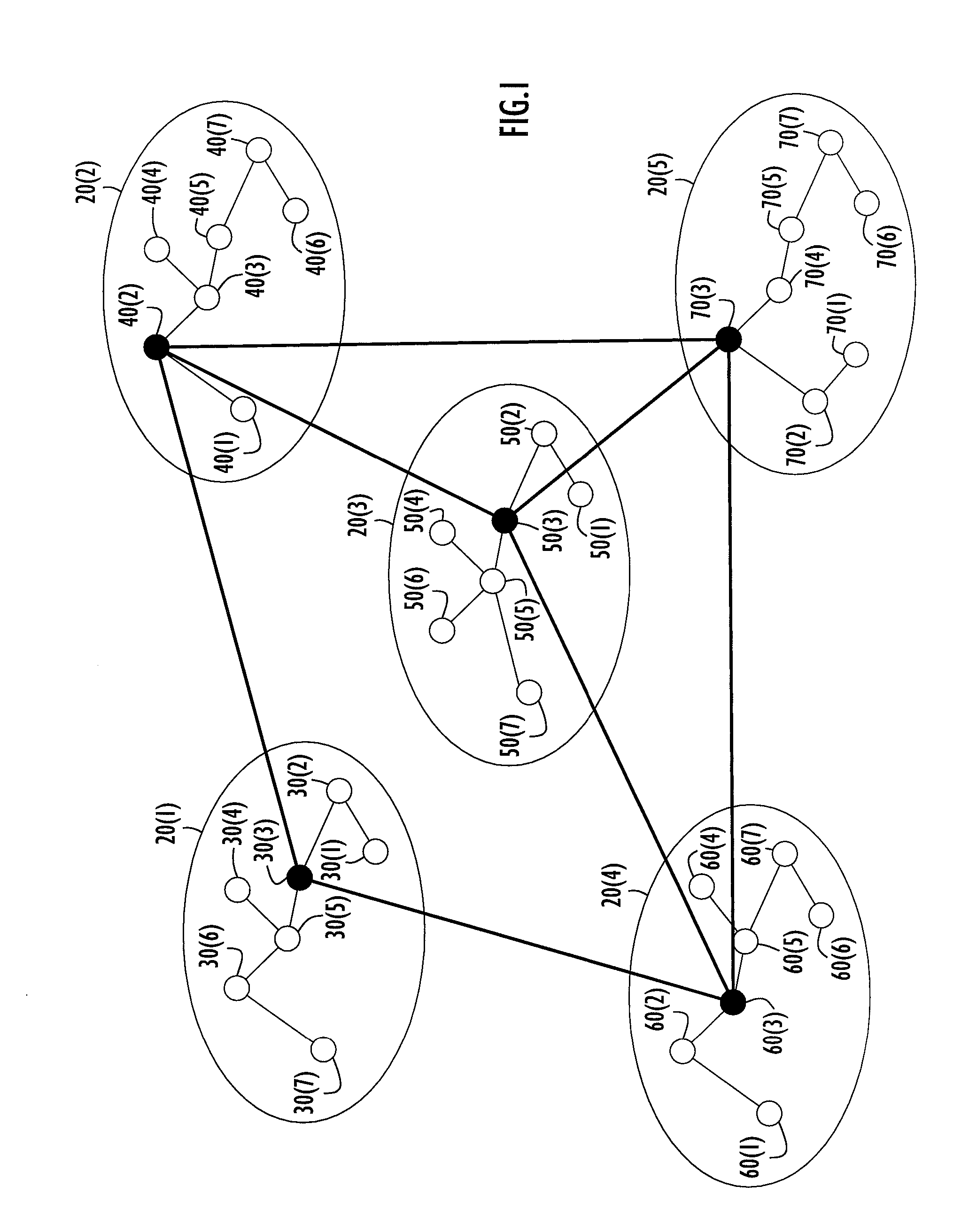
[0022]Reference is made first to FIG. 1 in which a conventional wireless ad-hoc communication network is shown at 10. The network 10 is organized into first and second tiers. The first tier comprises a plurality of so-called “islands”20(1) to 20(5). Each node joins an island and each island has a so-called “island head” indicated by the darker shaded node in an island. For example, island 20(1) comprises a plurality of nodes 30(1) to 30(7), and node 30(3) is the island head for island 20(1). Similarly, island 20(2) comprises nodes 40(1) to 40(7), and 40(2) is the island head. Island 20(3) comprises nodes 50(1) to 50(7) and node 50(3) is the island head. Island 20(4) comprises nodes 60(1) to 60(7) and node 60(3) is the island head. Island 20(5) comprises nodes 70(1) to 70(7) and node 70(3) is the island head. Those nodes affiliated with an island head are also called “island members”. Within an island there is a flat network architecture comprised of multiple hops.

[0023]The island he...


PUM


Abstract

Techniques for controlling access to a communication channel for each of a plurality of nodes in a wireless ad hoc communication network. According to one embodiment, each node uses a predetermined rule, such as a hash function, to compute which of a plurality of time slots during a contention window it is to attempt transmissions. Each node in the network follows the same rule to access the channel and as a result no additional overhead transmissions are required between the nodes. In addition, contention among different nodes is reduced when a node needs to repeat an attempt to make a transmission. When a node has data to transmit on the channel, it determines a time slot in the contention window period during which to attempt the transmission using a computation that is based on a number identifier assigned to the node, the number of time slots in the contention window period and a transmission count value that represents the number of attempts the node has made to make the transmission. According to another embodiment, nodes are assigned to slot groups based on the time slot computation and the groups are assigned to particular slots during successive blocks in a round robin fashion so as to ensure fair access to the communication channel.

Description

BACKGROUND OF THE INVENTION[0001]The present invention is directed to ad-hoc wireless communication networks in which devices that are nodes on the wireless network compete for access to the frequency channel in order to communicate with each other.[0002]One well known technique for controlling how devices access a shared channel is called ALOHA. In the ALOHA scheme, every node transmits as long as it has data available to transmit. If a collision is detected, the source node backs off and retransmits again after a timeout interval. An improvement to ALHOA is the so-called “slotted” ALOHA in which the transmitting node can only transmit within a slot boundary. However, collision probability is still high and unavoidable using the ALOHA schemes.[0003]There are two other well known channel access protocols: Carrier Sense Multiple Access (CSMA) and Time Division Multiple Access (TDMA). The TDMA scheme is mainly used for transmission that has certain requirements that must be met to mai...

Claims


Application Information

Patent Timeline
IPC IPC(8): H04J3/00
CPCH04W84/18H04W74/0816
Inventor LIU, YU-JIH
Owner STINGRAY IP SOLUTIONS LLC
Learn More