Needle Guidance With a Dual-Headed Laser

a laser and needle guidance technology, applied in the field of interventional radiology, can solve the problems of prior-art methods that may not provide proper precision and require a complicated sequence of steps

Active Publication Date: 2008-08-21
THE BOARD OF TRUSTEES OF THE LELAND STANFORD JUNIOR UNIV +1
View PDF2 Cites 22 Cited by
  • Summary
  • Abstract
  • Description
  • Claims
  • Application Information

AI Technical Summary

Problems solved by technology

Some prior-art methods may not provide proper precision.
Other prior-art methods may require a complicated sequence of steps.

Method used


Image

  • Needle Guidance With a Dual-Headed Laser
  • Needle Guidance With a Dual-Headed Laser
  • Needle Guidance With a Dual-Headed Laser

Examples


second embodiment

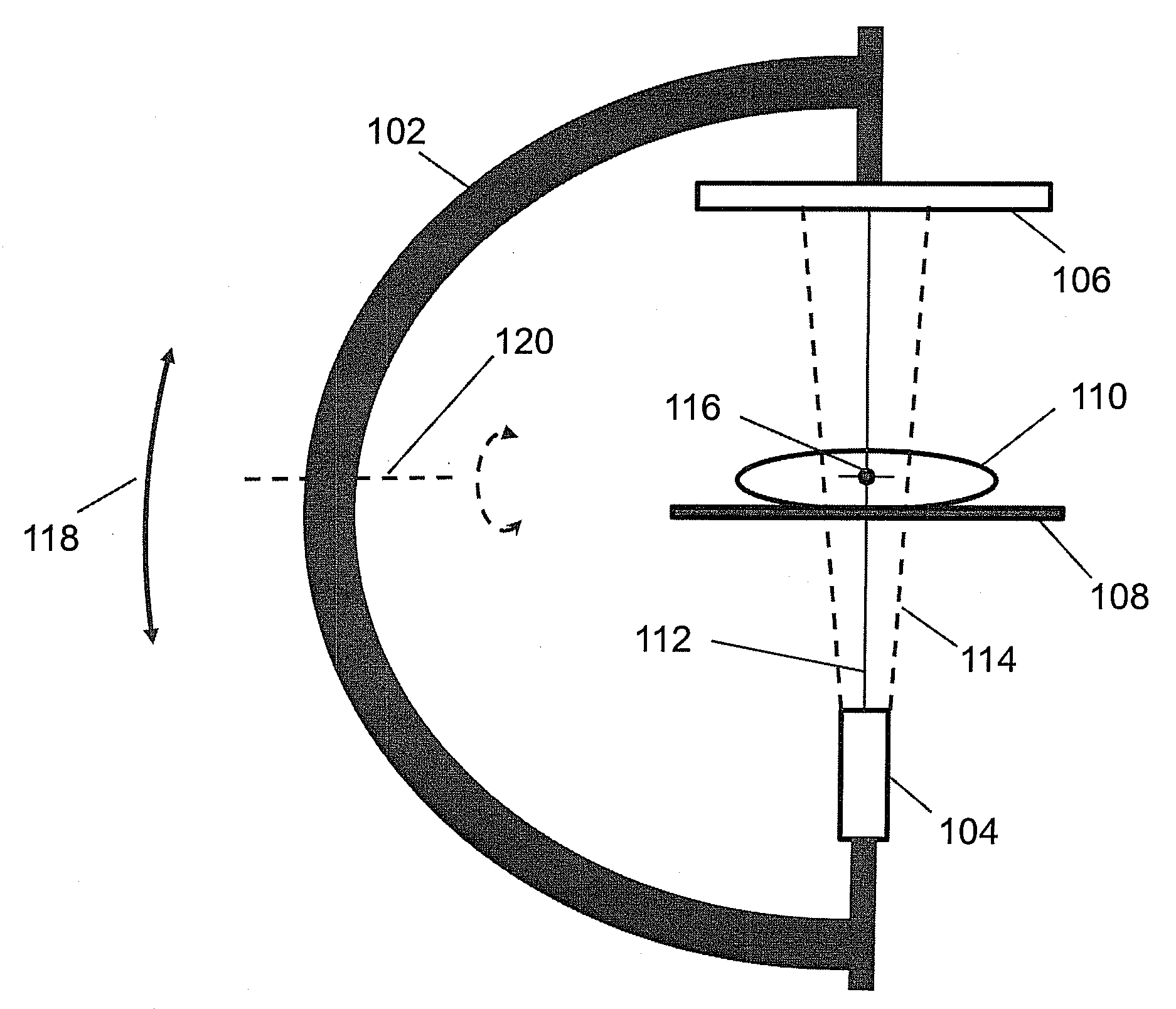
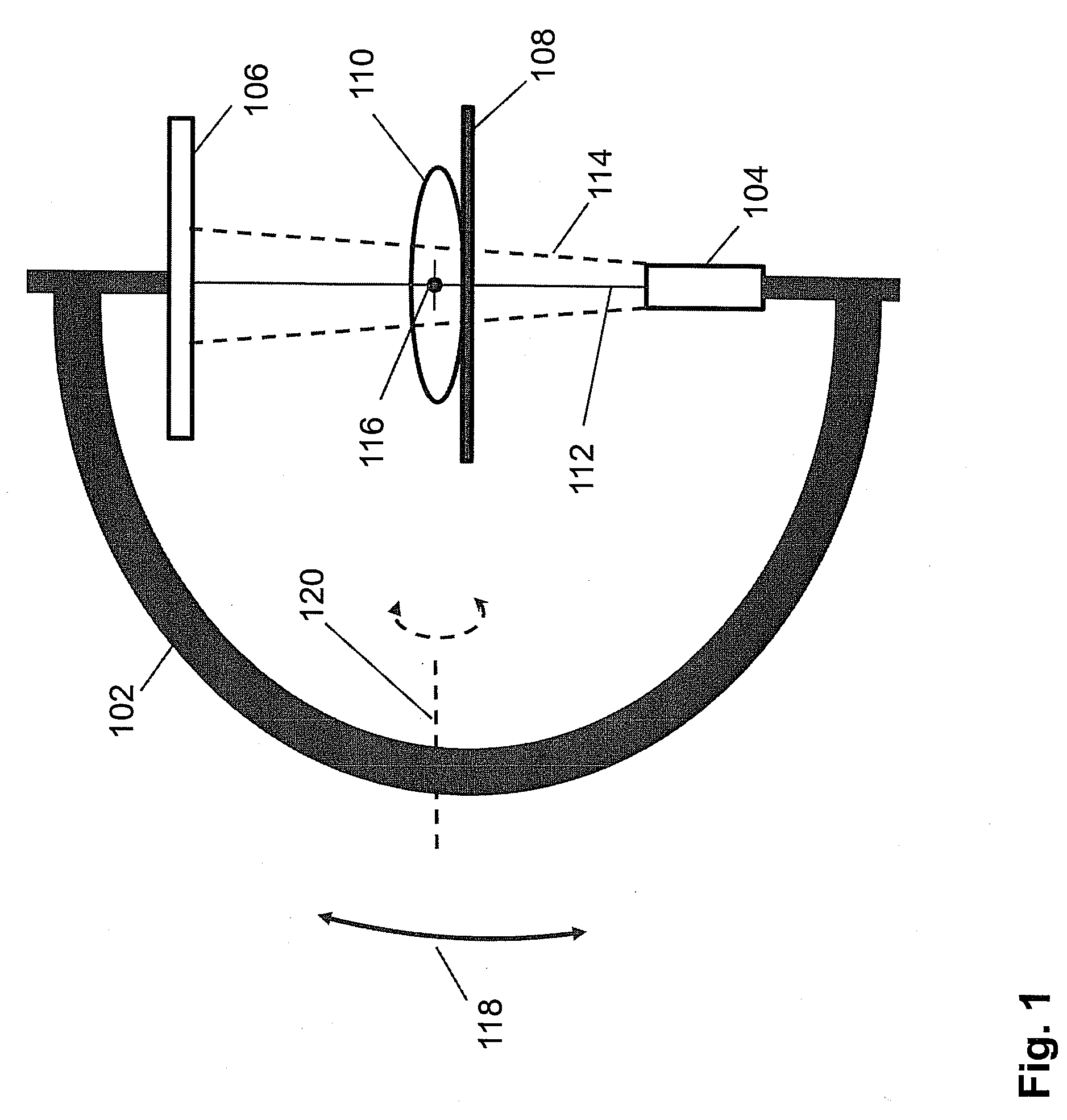
[0030]FIG. 4 shows a flowchart of a prior-art “bulls-eye view” method. This method is simpler because a needle is not used for initial positioning and alignment of the laser beam. Steps 402-410 are similar to steps 302-310. First, in step 402, the patient 110 is positioned in the C-arm 102. In step 404, a 3-D image of the patient is rendered from a previously acquired 3-D volume dataset and displayed on a monitor. In step 406, the positions of the target and skin entry point are marked on the display with graphical markers. In step 408, the target is aligned with the isocenter 116. In step 410, the axial ray 112, skin entry point, target, and center pixel of the detector 106 are aligned.

[0031]In step 412, a mechanical guide is installed over the center pixel of the detector 106. In step 414, a single-headed laser, which may be mounted on a mechanical arm, is positioned in the mechanical guide. The mechanical guide centers the axis of the laser beam over the center pixel of the detec...

third embodiment

[0038]The adjustment mechanism for aiming the beams comprises mechanical arm 532 described above. In one embodiment, mechanical arm 532 is adjusted manually. In another embodiment, the mechanical arm 532 is mounted on a stage which may be adjusted mechanically or electromechanically. In a third embodiment, the mechanical arm 532 may be a computer-controlled robotic arm.

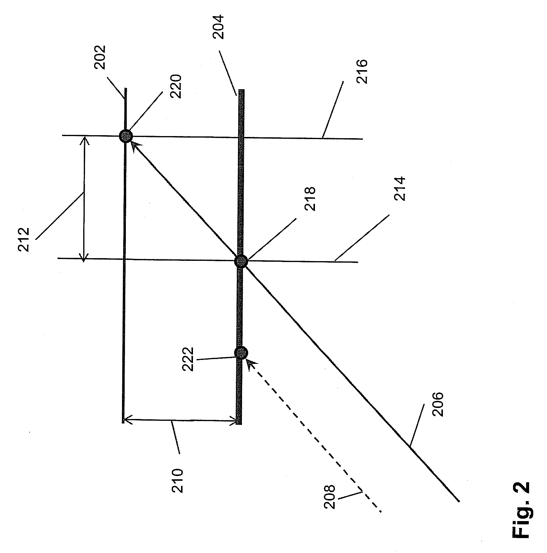
[0039]In practice, axes which are desired to be ideally collinear may not be truly collinear. Deviations from true collinearity, for example, may arise from manufacturing tolerances which may affect the collinearity of collimated beam 522 and collimated beam 524. Deviations from true collinearity, for example, may also arise from the precision in which mechanical arm 532 may be adjusted. The precision may affect the collinearity of collimated beam522 and needle trajectory 508. Herein, “collinear” axes refer to “substantially collinear” axes. Two axes are “substantially collinear” if the deviation from true collinearit...


PUM


Abstract

Disclosed are method and apparatus for guiding a needle during an interventional radiology procedure. The target and skin entry point are pre-determined in three-dimensional medical imaging scans. The needle trajectory is defined by the target and skin entry point, which is physically marked on the skin. A dual-headed laser emitting two laser beams is positioned and aligned such that one laser beam is aimed at the skin entry point and the other laser beam is aimed at an external reference point, which is determined such that the axis of the laser beam aimed at the skin entry point is substantially collinear with the needle trajectory. The needle is inserted while maintaining the axis of the needle substantially collinear with the axis of the laser beam aimed at the skin entry point.

Description

[0001]This application claims the benefit of U.S. Provisional Patent Application Ser. No. 60 / 890,700, filed on Feb. 20, 2007, which is incorporated herein by reference.BACKGROUND[0002]The present invention relates generally to interventional radiology, and more particularly to needle guidance.[0003]Interventional radiology (IR) permits minimally invasive diagnostic and surgical procedures. In an IR procedure, medical imaging techniques allow a radiologist (or other medical staff) to guide small surgical instruments or devices into the region of interest in a patient. Examples of medical imaging techniques include X-Ray fluoroscopy, X-Ray computed tomography (CT), and magnetic resonance imaging (MRI). Examples of regions of interest include blood vessels and organs such as a heart or liver. One category of procedures is referred to as percutaneous (through the skin). In a typical percutaneous procedure, a hollow needle punctures the skin, the needle is inserted, and the tip is positi...

Claims


Application Information

Patent Timeline
Patent Type & Authority Applications(United States)
IPC IPC(8): A61M5/158
CPCA61B19/201A61M5/427A61B2019/5238A61B2018/2025A61B2090/376A61B90/11
Inventor KUKUK, MARKUSGALANT, ADAM K.NAPEL, SANDY
Owner THE BOARD OF TRUSTEES OF THE LELAND STANFORD JUNIOR UNIV
Why Eureka
Try Eureka