Docking Buffer

a buffer and height adjustment technology, applied in the direction of loading/unloading, bridge applications, ways, etc., can solve the problems of not being able to adjust the buffer, affecting damage to the building door, building facade, or vehicle, etc., to achieve simple and robust design, enhance structural stability, and endanger the safe use of equipment

Active Publication Date: 2008-08-28
GRUNEWALD NICLAS
View PDF17 Cites 6 Cited by
  • Summary
  • Abstract
  • Description
  • Claims
  • Application Information

AI Technical Summary

Benefits of technology

[0020]The impact forces that occur can be advantageously diverted regardless of a building foundation by fastening the lower ends of the pillars to the road surface. Additional structural stability is achieved if the pillars are supported in the area of their upper end by a supporting beam, which in turn is preferably fastened to the road surface and / or a building foundation.
[0021]The embodiment of the invention provides for the bumper bar to have a gasket unit, which is preferably adjustable, particularly inflatable, with the gasket unit bridging a gap between the bumper bar and the transfer bridge. In this way, when loading or unloading in the case of a temperature-sensitive logistics chain, a safe seal against external air can be achieved so that no humidity can condense or freeze on the transfer bridge and thus endanger the safe use of equipment such as forklifts or pallet stackers. The gasket unit can have a simple and robust design if the gasket unit is inflatable. Such a gasket unit can also advantageously adjust to external parts on a vehicle so as to provide an especially good seal and not damage the vehicle. Because of its inflatability, the gasket unit can adjust extremely well to differing distances between the bumper bar and the vehicle / transfer bridge caused by different operating conditions and types of vehicle, while additional mechanical drives are not required because the gasket material is pressed into an appropriate shape by the incoming air. The gasket unit thereby advantageously extends across the width of the transfer bridge so that it seals the openings on either side of the transfer bridge to form a three-sided seal against the building opening.
[0022]This sealing effect is improved in that the gasket unit is U-shaped as viewed from the top and / or preferably formed with its free legs pointing in the direction of the docking bumper, i.e. in the direction of the truck. In this way, the gasket unit conforms better to the shape of the vehicle. It also forms a seal beyond the lateral edges of the transfer bridge by virtue of the fact that the gasket unit is wider than the transfer bridge.

Problems solved by technology

In this known configuration, it is not possible to adjust the buffer to a height above or below the ramp.
Nevertheless, the situation has repeatedly arisen wherein the ramp height is significantly lower than the height of the vehicle loading surface, with the result that the vehicle overshoots the edge of the ramp and thus in some circumstances damages the building door, building facade, or vehicle.
Such a docking buffer, which protrudes over the top edge of the ramp, interferes when opening the truck's door.
The solution to the problem of lowering the buffer when a truck is exerting pressure on the buffer is solved only insufficiently and thus disadvantageously with the state of the art.
It may also occur, however, that the loading surface of the docking truck is lower than the height of the ramp edge.
A special problem presents itself when, for specific reasons, e.g. temperature controlled logistics chains such as those for refrigerated buildings, no building wall is available to mount a docking buffer.
The disadvantages of these known concepts is that openings remain between the lateral seals and the transfer bridge, through which air exchange can occur between the outside air and the inside of the loading station.
These openings constitute a disadvantage, e.g. particularly in the case of logistics chains for deep frozen goods that require maintenance of a specific temperature or a specific climate for the items being transported.
Moreover, in the case of refrigerated buildings, the transfer bridges may freeze over because the warm air entering the area condenses existing moisture on the upper surface of the transfer bridge.
The resulting dew may also freeze, which presents a hazard to workplace safety.
A disadvantage of the known solutions is that an unsealed opening always remains on either side of the rear end of the vehicle and the transfer bridge.

Method used


Image

  • Docking Buffer
  • Docking Buffer
  • Docking Buffer

Examples


Embodiment Construction

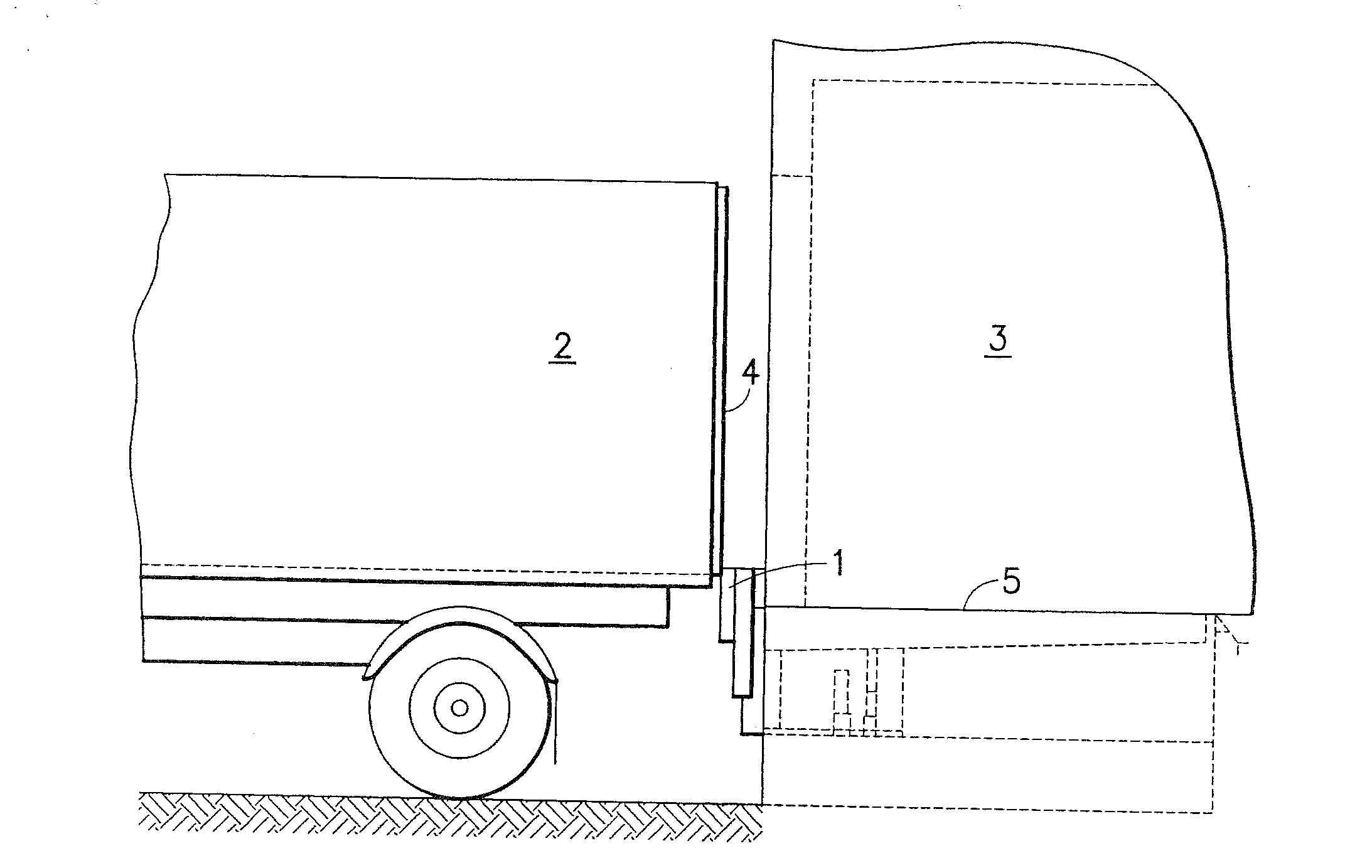
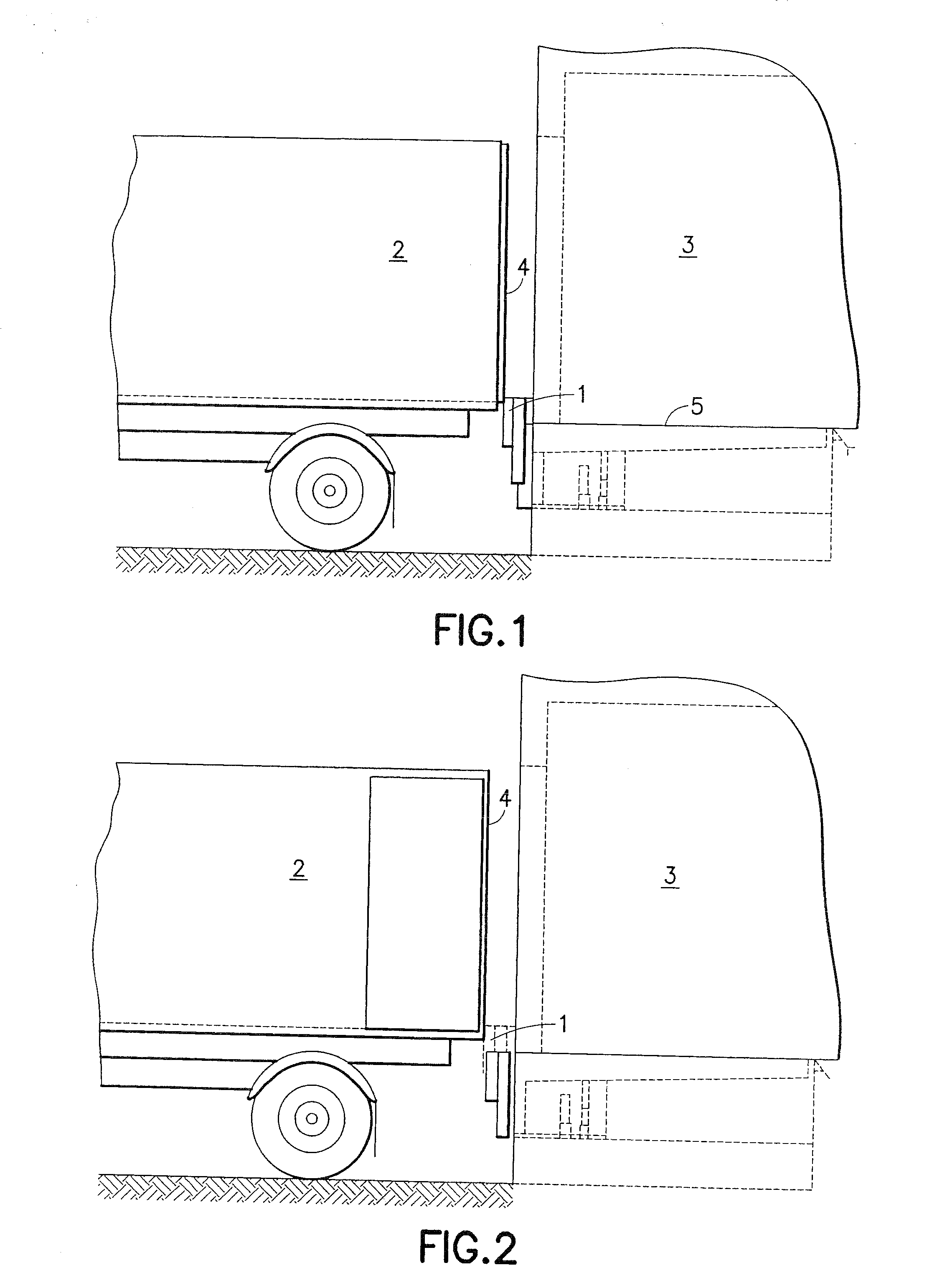
[0045]In FIGS. 1 and 2, 1 designates the docking buffer according to the invention, which is arrayed between a truck 2 and a building 3. FIG. 1 shows a situation in which the truck with closed doors 4 initially approaches docking buffer 1. In this process, the upper edge of the docking buffer is positioned so that it extends beyond the level of ramp edge 5. The docking buffer is thereby at a height that is sufficient to permit truck superstructures to be driven against the buffer. The buffer, however, obstructs opening of the doors 4. For this reason, the docking buffer is then moved out of the protective position according to FIG. 1 into the operating position shown in FIG. 2. In this position, the docking buffer no longer collides with the opening doors.

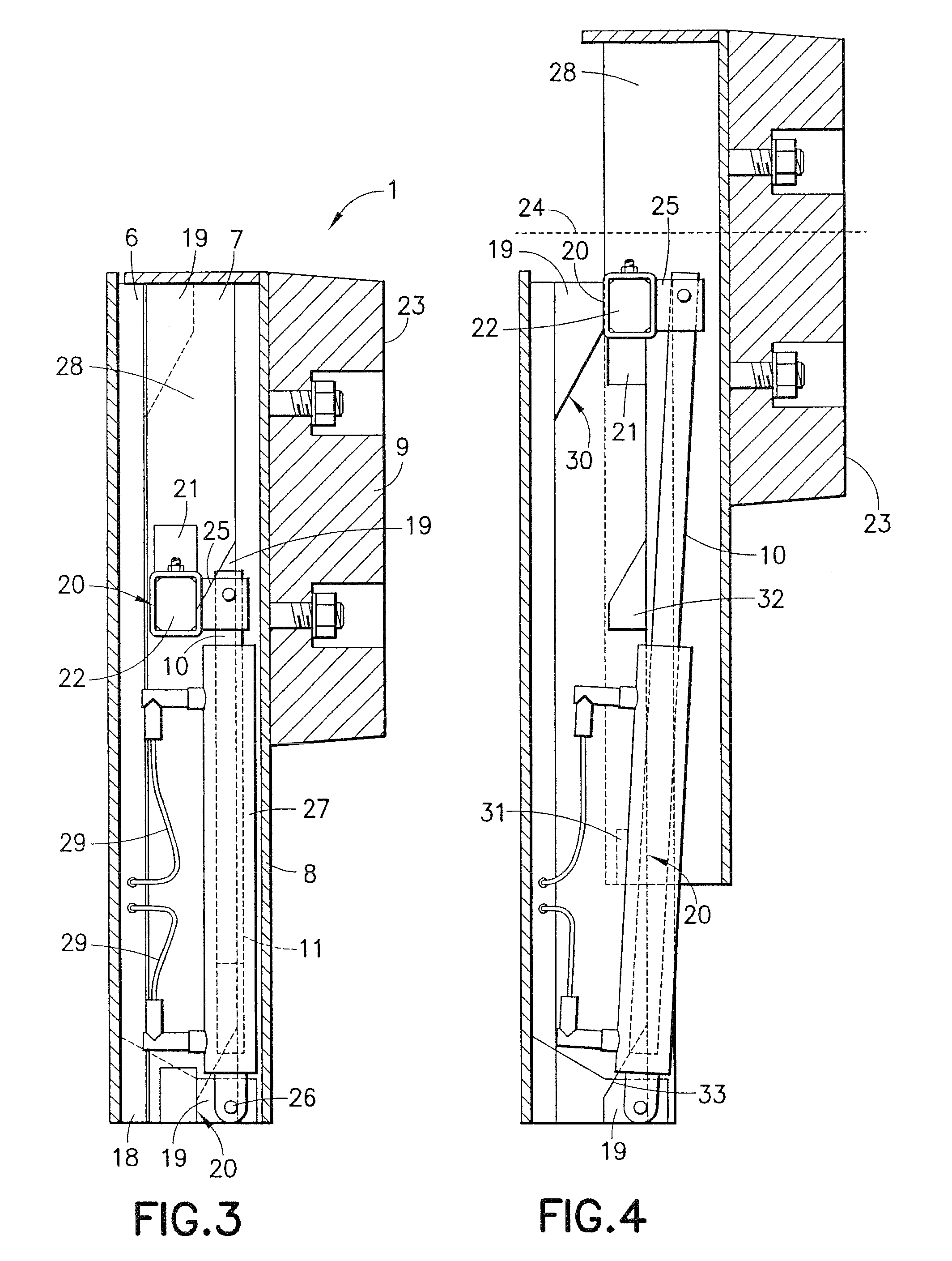
[0046]The design of the buffer according to the invention is shown in vertical section in FIG. 3. Docking buffer 1 essentially consists of a fixed assembly 6 and a movable assembly 7.

[0047]The movable assembly includes a buffer blo...


PUM


Abstract

A height-adjustable docking buffer is described for protecting facades when vehicles are docked in building openings. The docking buffer is made up of a fixed mounting frame and a height-adjustable buffer block for a loading ramp or a transfer bridge. The buffer block is designed as an essentially horizontal bumper bar, and includes an inflatable gasket, the ends of which are height-adjustably supported on two spaced, fixed mounting frames, preferably in the form of pillars. A method for operating the docking bar is also disclosed.

Description

PRIOR RELATED APPLICATIONS[0001]This patent application is a divisional patent application of U.S. patent application Ser. No. 10 / 543,929, filed May 10, 2006, which claims priority to and incorporates by reference in its entirety and claims priority to and incorporates by reference in their entireties German patent application Serial No. 103 05 565.7, filed Feb. 10, 2003 and German patent application Serial No. 103 13 268.6, filed Mar. 24, 2003 and PCT patent application, Serial No. PCT / EP2004 / 001214, filed Feb. 10, 2004.BACKGROUND[0002]1. Field of the Invention[0003]The invention relates to a height-adjustable docking buffer, particularly for protection during loading and unloading operations for vehicles at building openings, consisting of a mounting frame and a height-adjustable buffer block for a loading ramp or a transfer bridge.[0004]In addition, the invention relates to a process for operating a docking buffer.[0005]Trucks are loaded at warehouses almost exclusively on loadin...

Claims


Application Information

Patent Timeline
Patent Type & Authority Applications(United States)
IPC IPC(8): E01D18/00B65G69/00B65G69/28
CPCB65G69/001B65G69/2876B65G69/008
Inventor GRUNEWALD, NICLAS
Owner GRUNEWALD NICLAS
Why Eureka
Try Eureka