Automatic thin-section manufacturing system

a manufacturing system and thin-section technology, applied in the field of automatic thin-section manufacturing system, can solve the problems of inability to recover (flatten) in the subsequent flattening process step, difficulty in thin-section cutting of embedded blocks, and inability to break the thin-section in some cases, so as to achieve smooth delivery, improve the degree of freedom, and maintain the effect of postur

Active Publication Date: 2008-08-28
SAKURA FINETEK JAPAN
View PDF12 Cites 29 Cited by
  • Summary
  • Abstract
  • Description
  • Claims
  • Application Information

AI Technical Summary

Benefits of technology

[0023]After the cutting blade is fixed, a transportation unit moves the embedded block relative to the holder in order to thinly cut the embedded block with the press-fixed cutting blade. In this manner, thin sections are manufactured by cutting them out from the embedded block. Furthermore, because the holder is provided at a predetermined rake angle with respect to the surface of the embedded block, the cutting blade is provided similarly at the rake angle. Thus, sectioning can be smoothly performed at the predetermined rake angle. Further, after sectioning is completed for predetermined times, the control unit releases the pressing of the first pressing member, and, at the same time, operates the conveyor unit to convey a new cutting blade onto the mounting plane. In this manner, the used cutting blade remaining mounted on the mounting plane is pushed by the new cutting blade and slides out of the mounting plane. Then, when the new cutting blade comes to the predetermined position, the first pressing member presses the cutting blade to provide the cutting blade for sectioning. That is, the cutting blades are automatically exchanged every predetermined times of sectioning. Accordingly, the cutting blades are exchanged without involving any human power; hence, the burden on the operators can be minimized. Furthermore, high quality thin sections can be manufactured because sharp-edged cutting blades are provided constantly.
[0035]In accordance with the invention, there is provided an automatic thin-section manufacturing system capable of manufacturing thin sections by thinly cutting an embedded block at an already set rake angle while automatically exchanging the cutting blades, thereby minimizing the burden of the operator by eliminating the cutting blade exchange operation which had been a burden to the operators. Furthermore, high quality thin sections can be manufactured because sharp-edged cutting blades are provided constantly for sectioning. Moreover, thin sections of the same quality can be continuously manufactured because the cutting blade can be exchanged while maintaining the cutting edge at the same amount of protrusion.

Problems solved by technology

Firstly, the thin section obtained by main cutting is released in water to set afloat.
However, the section-slides manufacturing apparatus described in the JP-A-2004-28910 above still had the following problems to be solved.
If thin cutting should be carried out with a blunt-edged cutting blade, difficulties were found in thinly cutting the embedded block into thin sections of desired thickness (for instance, from 3 μm to 5 μm).
Furthermore, there were possibilities of breaking the thin sections in some cases.
Moreover, there was a possibility of applying too high a load to compress (deform) the thin section, thereby making it unfeasible to recover (flatten) in the subsequent flattening process step.
Thus, the operators were still hard-pressed, and the apparatus was not easy for handling.
Thus, in case of exchanging the cutting blade, the cutting blade must be kept supported, or it slides down by the gravity and cannot be set at the regular position.
This laid additional burden on the operator.

Method used


Image

  • Automatic thin-section manufacturing system
  • Automatic thin-section manufacturing system
  • Automatic thin-section manufacturing system

Examples


Embodiment Construction

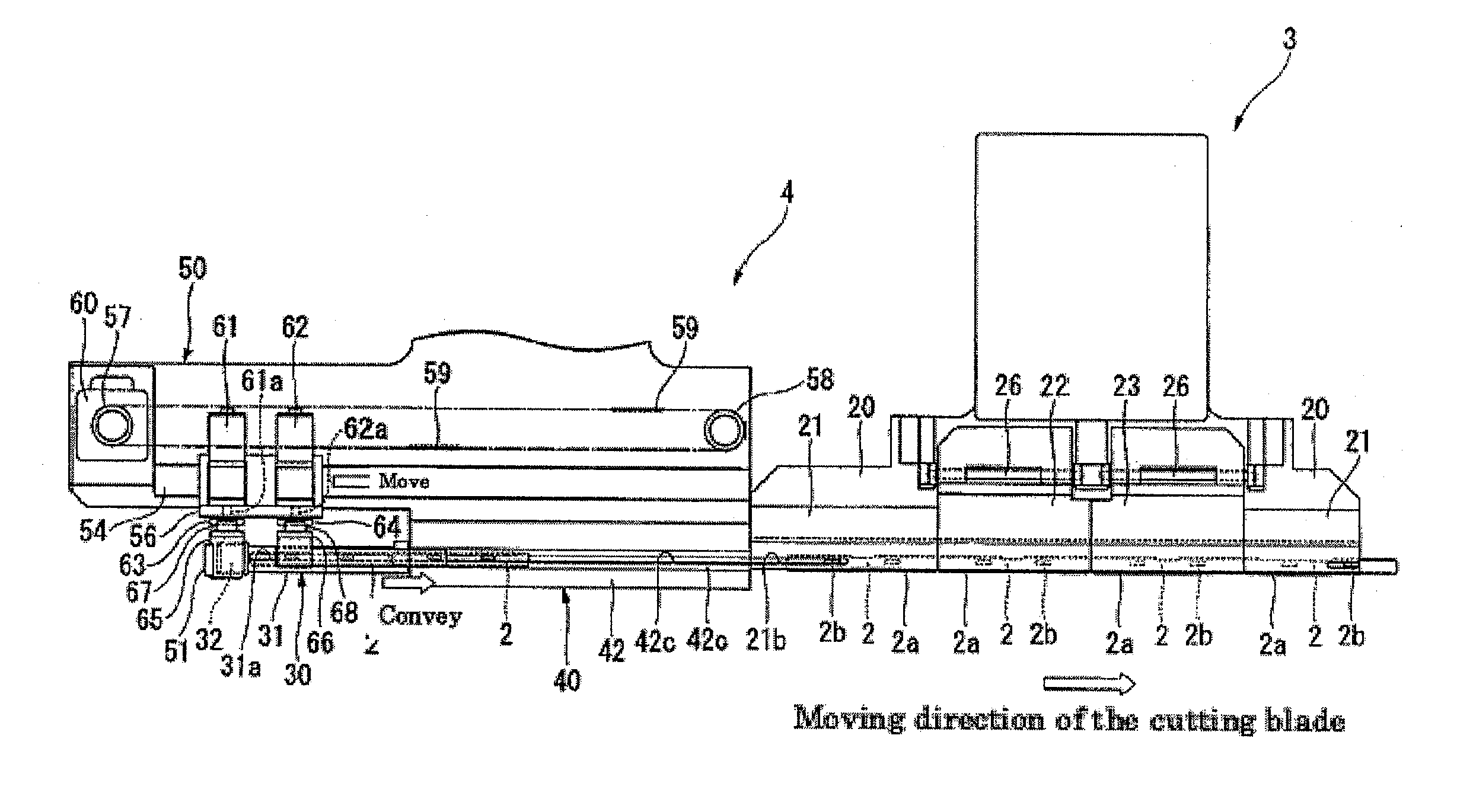
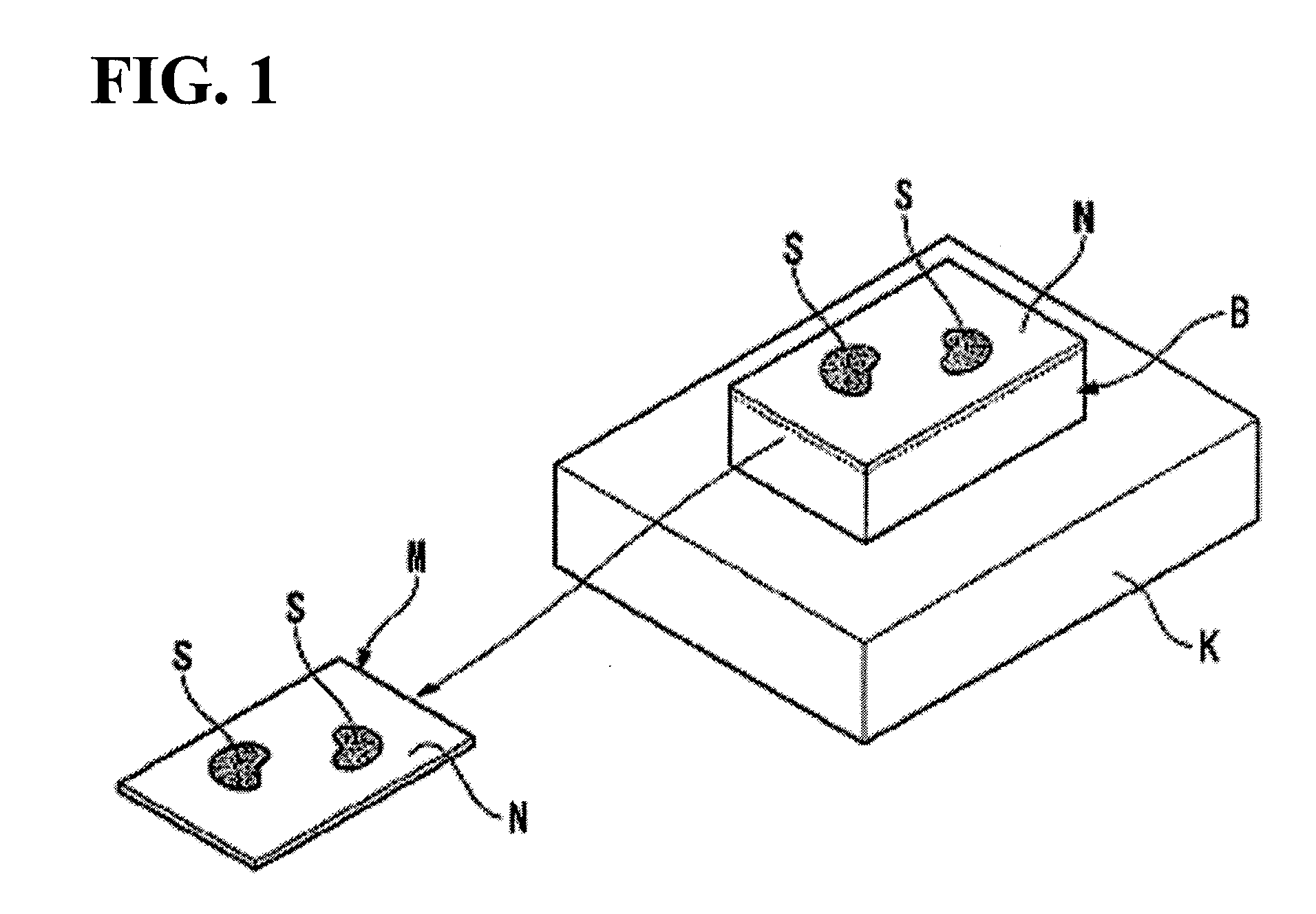
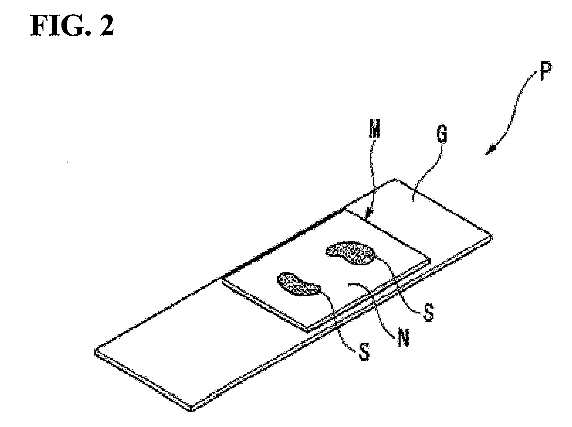
[0055]An embodiment of an automatic thin-section manufacturing system according to the invention is described below by making reference to FIGS. 1 to 19. Referring to FIG. 1, the automatic thin-section manufacturing system according to the invention is a system which thinly cuts an embedded block B comprising an embedding medium N having embedded therein a biological sample S (for instance, ultra-thin sections from 3 μm to 5 μm in thickness), at a preliminarily set rake angle θ, to manufacture a thin section M.

[0056]The embedded block B is prepared by paraffin-substituting the water contained in the formalin-fixed biological sample S, and then solidifying the surroundings with an embedding agent N such as paraffin and the like to obtain a block. Thus, at this moment, the biological sample S is obtained embedded in paraffin. As the biological sample S, for instance, there can be used a tissue of organs and such taken out from human bodies and laboratory animals and the like, which is...


PUM

PropertyMeasurementUnit
thicknessaaaaaaaaaa
thicknessaaaaaaaaaa
thicknessaaaaaaaaaa

Abstract

An automatic thin-section manufacturing system for manufacturing thin sections by thinly cutting out an embedded block having embedded therein a biological sample while setting said embedded block at a predetermined rake angle, and said system comprising: a long cutting blade having a cutting edge on one end; a holder disposed in such a manner that it makes the rake angle with respect to the surface of the embedded block; a mounting plane which is provided to the front end of the holder, on which plural cutting blades are mounted and aligned with their cutting edges exposed to the outer side; an adsorptive member provided along the mounting plane, which maintains the posture of the cutting blades by adsorbing the base end side of the cutting blades mounted on the mounting plane; a first pressing member provided to the holder, which presses, among the plural cutting blades that are mounted and aligned on the mounting plane, the cutting blade allocated to the predetermined position against the mounting plane; a conveyor unit which slides out the cutting blades that are linearly aligned on the mounting plane, by sequentially conveying the plural cutting blades to feed them one by one on the mounting plane; a transportation unit which moves the embedded block relative to the holder, such that the cutting blade pressed by the first pressing member cuts out the thin section from the embedded block; and a control unit which, after performing thin sectioning for a predetermined time, exchanging the cutting blade used for the thin sectioning by operating the conveyor unit to slide out the cutting blades.

Description

[0001]This application claims priority under 35 U.S.C. §119 to Japanese Patent Application No JP2007-047445 filed Feb. 27, 2007, the entire content of which is hereby incorporated by reference.BACKGROUND OF THE INVENTION[0002]1. Field of the Invention[0003]The present invention relates to an automatic thin-section manufacturing system which manufactures thin sections by thinly cutting an embedded block containing embedded therein a biological sample.[0004]2. Background Art[0005]Conventionally, a microtome has been known in general as a tool to use in preparing thin section slide samples for physicochemical experiments and microscopic observations. The thin section slides are prepared by fixing thin sections about several micrometers (for instance, from 3 μm to 5 μm) in thickness on a substrate such as a glass slide. A generally employed method for preparing a thin section sample using a microtome is described below.[0006]An embedded block is prepared by first subjecting a formalin-f...

Claims


Application Information

Patent Timeline
Patent Type & Authority Applications(United States)
IPC IPC(8): B26D7/06
CPCG01N1/06Y10T83/6492Y10T83/9459
Inventor FUJIWARA, HIROHITOITO, TETSUMASAFUJIMOTO, KOJIMIYATANI, TATSUYA
Owner SAKURA FINETEK JAPAN
Why Eureka
Try Eureka