Insert molded leadframe assembly

a technology of inserting lead frame and assembly, which is applied in the manufacture of contact parts, coupling device details, coupling device connections, etc., can solve the problems of affecting the strength and integrity of the resulting solder connection, and affecting the formation of electrical connections

Inactive Publication Date: 2008-08-28
FCI AMERICAS TECH LLC
View PDF74 Cites 13 Cited by
  • Summary
  • Abstract
  • Description
  • Claims
  • Application Information

AI Technical Summary

Benefits of technology

[0004]The invention provides an insert molded leadframe assembly (IMLA) that may

Problems solved by technology

Such uneven distribution can result in differences in the collapsing properties and the height of the solder balls as the solder balls are melted to form electrical connections.
These factors degrade the strength a

Method used


Image

  • Insert molded leadframe assembly
  • Insert molded leadframe assembly
  • Insert molded leadframe assembly

Examples


Embodiment Construction

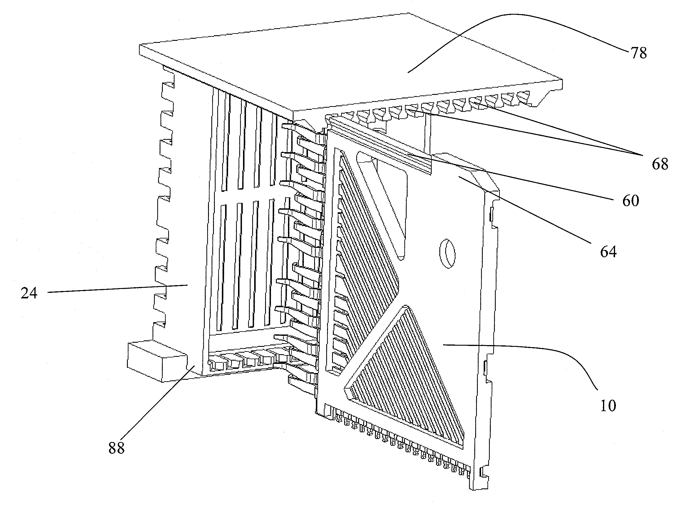
[0014]The figures depict an embodiment of an insert molded leadframe assembly (IMLA) for use in a right-angle ball-grid array (BGA) connector. The IMLA is described in conjunction with this particular type of connector for exemplary purposes only; alternative embodiments of the IMLA can be configured for use with virtually any type of surface-mounted connector.

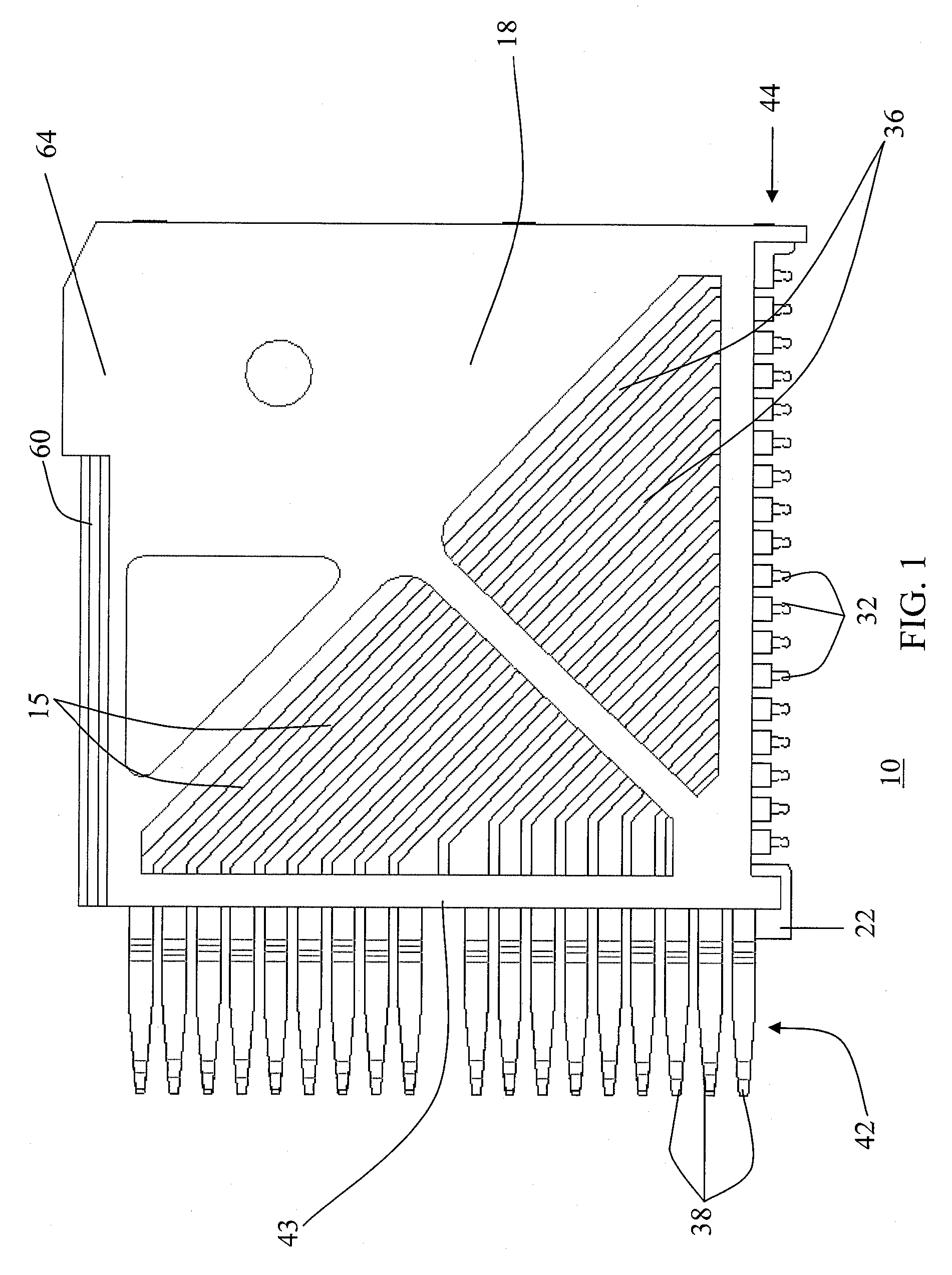
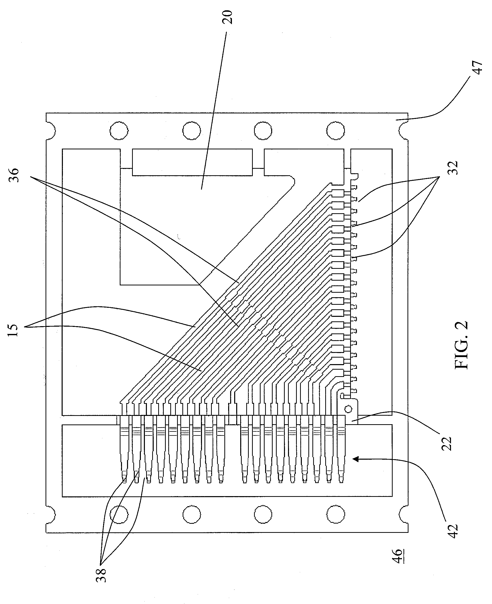
[0015]FIG. 1 depicts an example embodiment of an IMLA 10. As shown, the IMLA 10 may include a plurality of electrically conductive contacts 15 that extend through a leadframe housing 18. The IMLA 10 may also include a mass 20 (FIG. 2) embedded within the leadframe housing 18, and an alignment member 22 for positioning the IMLA 10 in a connector housing 24 (shown in FIGS. 5-6). A void in the plastic, shown as an exemplary right angle triangle in FIGS. 1 and 5-8B, may also be used to shift the center of gravity of the electrical connector. The void may take any shape or size.

[0016]Each contact 15 may include a terminal end 32, a...


PUM


Abstract

An insert molded leadframe assembly (IMLA) for an electrical connector is disclosed. The IMLA may include an array of electrically conductive contacts, a dielectric leadframe housing overmolded onto the array of contacts, and a mass disposed within the leadframe housing. The additional mass may shift the IMLA's center of gravity, thereby providing a counterbalance to a non-proportional ball-grid array connector.

Description

FIELD OF THE INVENTION[0001]The invention relates generally to electrical connectors. More specifically, the invention relates to an insert molded lead frame assembly.BACKGROUND OF THE INVENTION[0002]Electrical connectors, such as ball-grid array (BGA) connectors, are usually mounted on the surface of a substrate using multiple solder connections. The solder connections act as electrical and mechanical connections between the substrate and contact pads on the connector.[0003]The weight of some BGA connectors is not distributed evenly across the solder balls (or other fusible elements). For example, the center of gravity of some BGA connectors, such as right angle BGA connectors, may be offset from the geometric center thereof to an extent that causes the connector to tilt (or tip) on the substrate. Such tilting can vary the pressures on the solder balls of the ball-grid array. In other words, the weight of the connector may be distributed unevenly among the solder balls. Such uneven...

Claims


Application Information

Patent Timeline
IPC IPC(8): H01L23/12
CPCH01R13/514H01R12/712H01R43/24H01R43/16
Inventor MINICH, STEVEN E.
Owner FCI AMERICAS TECH LLC
Why Eureka
Try Eureka