Thermal-electron source

a technology of electro-electron source and thermal-electron source, which is applied in the manufacture of electric discharge tube/lamp, electrode system, solid thermionic cathodes, etc., can solve the problems of thermal damage, insufficient to meet the current increasing demand for a lower operating temperature, and insufficient to realize a large-area thermal-electron source,

Inactive Publication Date: 2008-08-28
KK TOSHIBA
View PDF1 Cites 14 Cited by
  • Summary
  • Abstract
  • Description
  • Claims
  • Application Information

AI Technical Summary

Problems solved by technology

Although an oxide cathode, such as barium oxide (BaO)-based cathode, is widely used as the thermionic cathode that functions at a low temperature, it is still not sufficient to meet a currently increasing demand for a lower operating temperature.
However, even if the diamond is used as the thermionic cathode material, the thermionic cathode needs to be heated, resulting in a thermal damage due to heat radiation from the thermionic cathode on other members around the thermionic cathode.
The thermal damage on the other members makes it difficult to realize an integration of the thermal-electron source and to realize a large-area thermal-electron source.
Furthermore, because a power consumption of the thermal-electron source is large, a power efficiency of the thermal-electron source is degraded.
In addition, because a temperature of the thermionic cathode is required to reach a predetermined point to emit a thermal electron, the thermionic cathode can hardly make a prompt response to an applied current at a low temperature.
Therefore, the power consumption is increased due to a standby energy necessary for the constant heating, resulting in a degradation of the power efficiency of the thermal-electron source.

Method used


Image

  • Thermal-electron source
  • Thermal-electron source
  • Thermal-electron source

Examples


first embodiment

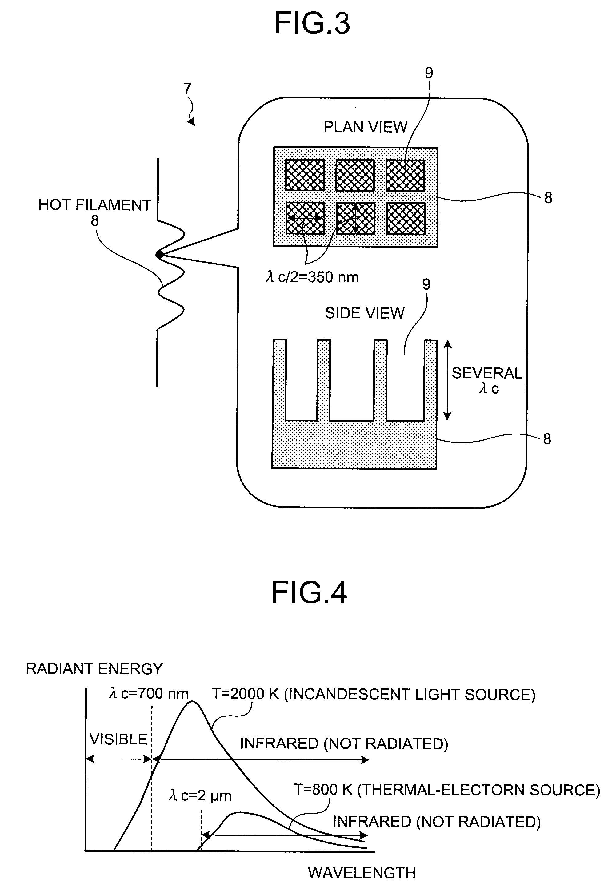
[0031]The thermal-electron source is configured based on the above principle. In the normal thermal-electron source, an extra electric power for heating is required for compensating energy loss caused by the infrared radiation from the filament as the thermionic cathode and heat conduction by a supporting member of the filament; however, large amount of the infrared radiation occurs because the filament temperature is high (1000° C. or higher).

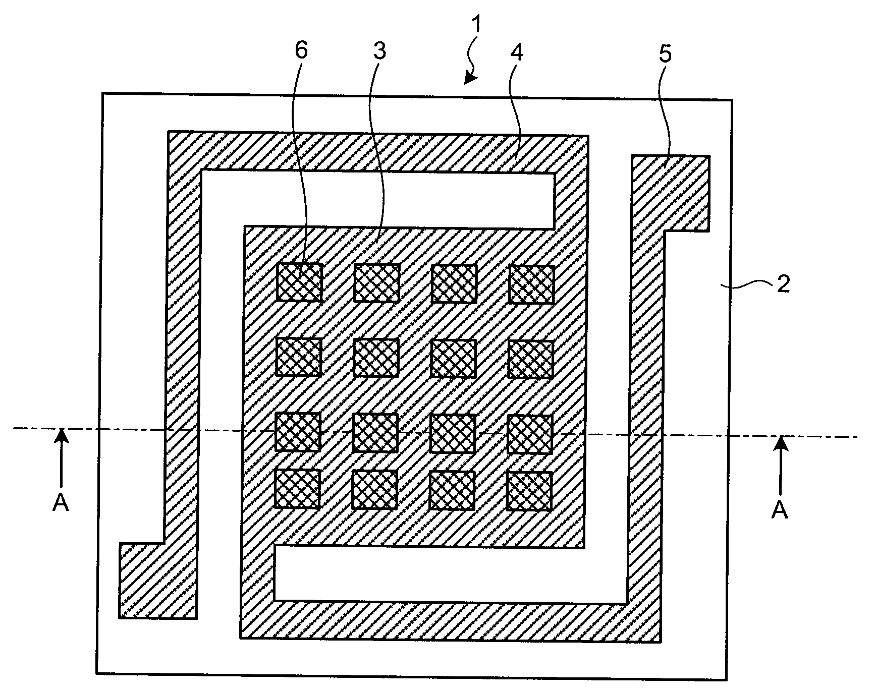
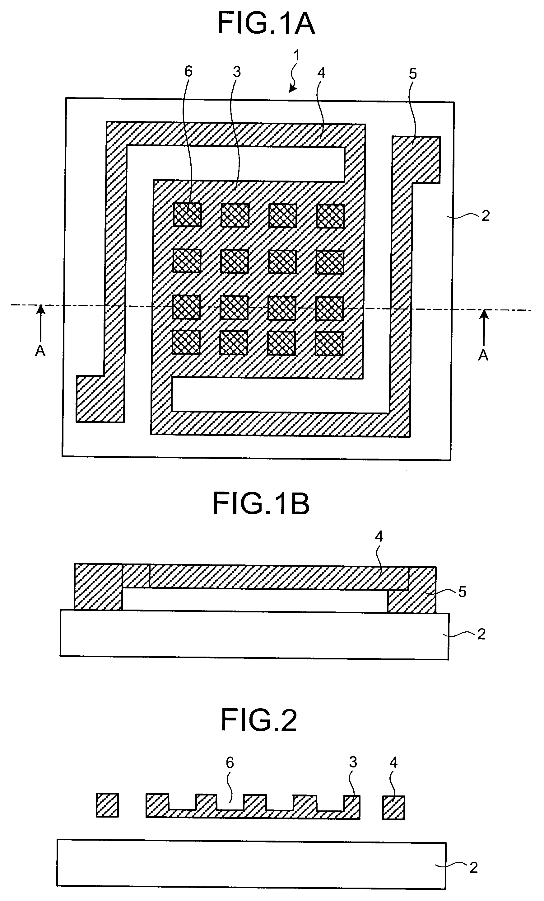
[0032]On the other hand, in the thermal-electron source 1, a number of the microcavities 6 are formed on the surface of the thermionic cathode 3, so that it is possible to suppress the infrared radiation even when the heating is performed by applying current via the fixing member 5. In this case, because a temperature of the filament is low compared with that of the incandescent light source, it is possible to suppress most of the infrared radiation, even when the wavelength of the infrared radiation is longer than that of the incandescent li...

second embodiment

[0053]The supporting member 24 supports the thermionic cathode 23. The fixing member 25 fixes the supporting member 24 to the substrate 2. Accordingly, the thermionic cathode 23 is configured in such a manner that the thermionic cathode 23 is separated from the substrate 2 and floated in the air. In the second embodiment, the supporting member 24 and the fixing member 25 are made of polysilicon film in connection with the method of manufacturing the thermal-electron source 21. However, the supporting member 24 and the fixing member 25 can be made of other materials. The reflector 26 is provided on the substrate 2 in such a manner that the size of the reflector 26 approximately corresponds to the size of the thermionic cathode 23 provided over the reflector 26, and reflects the infrared radiation from the bottom surface of the thermionic cathode 23. The reflector 26 is made of tungsten (W).

[0054]With the reflector 26 provided, the infrared radiation from the bottom portion of the the...


PUM


Abstract

A thermal-electron source includes a substrate; and a thermionic cathode having conductivity, and being provided on the substrate, and including a plurality of microscopic pores on a surface of the thermionic cathode.

Description

CROSS-REFERENCE TO RELATED APPLICATIONS[0001]This application is based upon and claims the benefit of priority from the prior Japanese Patent Application No. 2007-49063, filed on Feb. 28, 2007; the entire contents of which are incorporated herein by reference.BACKGROUND OF THE INVENTION[0002]1. Field of the Invention[0003]The present invention relates to a thermal-electron source that emits thermal electron.[0004]2. Description of the Related Art[0005]A thermionic cathode using a thermal electron which is emitted from a material during heated to high temperature is used as an electron source of a vacuum tube such as an X-ray tube and a high-frequency electron tube that function in vacuum, and as an electron source of a discharge tube such as a fluorescent tube that functions in gas. A current density of the thermal electron in the thermionic cathode is determined based on a work function of the surface and an operating temperature, of the thermionic cathode. If the work function of ...

Claims


Application Information

Patent Timeline
Patent Type & Authority Applications(United States)
IPC IPC(8): H01J1/16
CPCH01J1/16
Inventor ONO, TOMIOSAKAI, TADASHISAKUMA, NAOSHISUZUKI, MARIKO
Owner KK TOSHIBA
Why Eureka
Try Eureka