Drive unit

a technology of friction drive and drive unit, which is applied in piezoelectric/electrostrictive/magnetostrictive devices, piezoelectric/electrostrictive/magnetostrictive devices, piezoelectric/electrostrictive/magnetostriction machines, etc., can solve the problems of delayed movement of the center of gravity vibration of the driven member, so as to reduce the accumulation of vibration energy in the audio rang

Inactive Publication Date: 2008-08-28
KONICA MINOLTA OPTO
View PDF8 Cites 6 Cited by
  • Summary
  • Abstract
  • Description
  • Claims
  • Application Information

AI Technical Summary

Benefits of technology

[0016]According to the present invention, since the drive speed of the drive unit is decreased in response to a delay of equipment to be used or a member to be driven by the drive unit, accumulation of vibration energy in the audio range can be reduced.

Problems solved by technology

Although a friction-drive type drive unit is excellent in responsivity and capable of giving large driving torque to a driven member, which is an object to be driven, yet the movement of the center of gravity of the driven member may be delayed behind a sliding displacement of the frictional engagement member because of flexure of the driven member or the like.
Such delay of the movement of the center of gravity of the driven member could cause the driven member to be vibrated.
However, the driven member is accelerated with delay to the frictional engagement member so that differences between the frictional engagement member and the driven member are accumulated as elastic energy, causing the driven member to be vibrated.

Method used


Image

  • Drive unit
  • Drive unit
  • Drive unit

Examples


Embodiment Construction

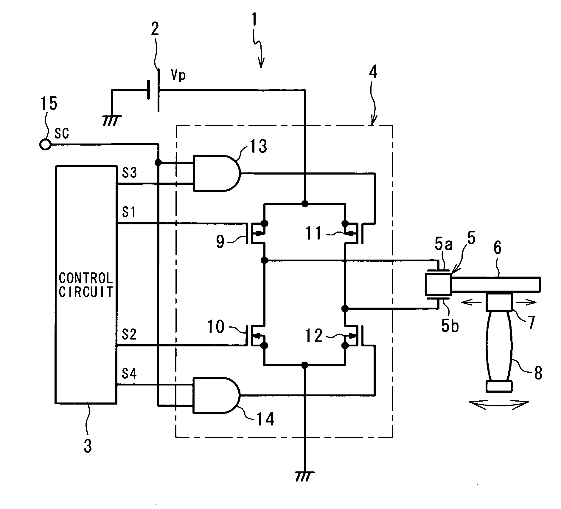
[0025]FIG. 1 shows a construction of a drive unit 1 according to a first embodiment of the invention. The drive unit 1 has a drive circuit 4 to which a DC power supply 2 of a voltage Vp (V) and a control circuit 3 are connected, a piezoelectric element (electromechanical transducer element) 5 to electrodes 5a, 5b of which an output of the drive circuit 4 is applied, a shaft-like vibrating member 6 whose one end is fixed to the piezoelectric element 5, and a frictional engagement member 7 to be engaged with the vibrating member 6 by frictional force. The drive unit 1 is a lens drive unit in which the piezoelectric element 5 is fixed to its casing and the frictional engagement member 7 holds a lens (driven member) 8.

[0026]The piezoelectric element 5 is so designed as to expand and contract in an axial direction of the vibrating member 6 in response to a voltage applied to between the electrodes 5a, 5b. Expansion and contraction of the piezoelectric element 5 causes the vibrating membe...


PUM


Abstract

The drive unit, being small in drive noise, includes an electromechanical transducer element 5, a vibrating member 6, a frictional engagement member 7, and a drive circuit 4 which is enabled to apply either a periodic main drive voltage that allows the frictional engagement member 7 to be slidingly displaced, or a periodic sub drive voltage that allows the frictional engagement member 7 to be slidingly displaced at a speed slower than that of the main drive voltage, to the electromechanical transducer element 5, wherein the drive circuit 4 applies the sub drive voltage to the electromechanical transducer element 5 during at least part of a time period of 25 msec counted from a drive start or a drive end of the frictional engagement member 7.

Description

[0001]This application is based on application No. 2007-046782 filed in Japan, the contents of which are hereby incorporated by reference.BACKGROUND OF THE INVENTION[0002]The present invention relates to a friction-drive type drive unit.[0003]There is publicly known a friction-drive type drive unit in which a shaft-like vibrating member is reciprocatively displaced asymmetrically in its axial direction by an electromechanical transducer element such as a piezoelectric element so that a frictional engagement member frictionally engaged with the vibrating member is slidingly displaced relative to the vibrating member (which may be done in two modes that the frictional engagement member is moved and that the vibrating member is moved). JP2001-211669A discloses a circuit for applying a rectangular-wave drive voltage to expand and contract an electromechanical transducer element asymmetrically.[0004]Although a friction-drive type drive unit is excellent in responsivity and capable of giv...

Claims


Application Information

Patent Timeline
Patent Type & Authority Applications(United States)
IPC IPC(8): H01L41/04
CPCH02N2/067H02N2/025
Inventor YOSHIDA, RYUICHI
Owner KONICA MINOLTA OPTO
Why Eureka
Try Eureka