Interactive battery charger for electric vehicle

a technology for electric vehicles and chargers, applied in hybrid vehicles, electric controllers, instruments, etc., can solve the problems of large peak power loads and transients of utilities, low quality power on the grid from the larger, and low efficiency of fast response power plants during the off hours, so as to optimize grid and power plant use, and reduce the effect of electric power consumption

Active Publication Date: 2008-08-28
FORD GLOBAL TECH LLC
View PDF7 Cites 259 Cited by
  • Summary
  • Abstract
  • Description
  • Claims
  • Application Information

AI Technical Summary

Benefits of technology

[0010]Information regarding the magnitude of electric energy required to fully charge the vehicle's battery, the duration and load that will put on the utility grid while performing the charging, and user's preferred time to complete the charge, can be transmitted to the electric utility or a user power control center. The utility can use the information to optimize its plant usage by knowing the future load demand or direct the vehicle charge cycle timing to optimize the grid and power plant use. The benefits to the user and utility result in lower cost electric power for the user and better plant use by the utility. If the information is used by a home power center, it is becoming common for the cost of power to the user to vary based on utility load. The charge information could be used to obtain the lowest cost vehicle charge for the user.
[0011]The charge system better optimizes the utility load through the entire day instead of using interruptible power which only optimizes the load during high utility power peaks.

Problems solved by technology

With the development of plug-in hybrid electric vehicles and other plug-in electric vehicles, the demand on the utility grid power can be significant and can cause large peak power loads and transients for the utility.
These fast response power plants are typically less efficient than the slower responding power plants.
The lower-cost, high quality power on the grid from the larger, slower response power plants during the off hours is often underutilized.

Method used


Image

  • Interactive battery charger for electric vehicle
  • Interactive battery charger for electric vehicle
  • Interactive battery charger for electric vehicle

Examples


Embodiment Construction

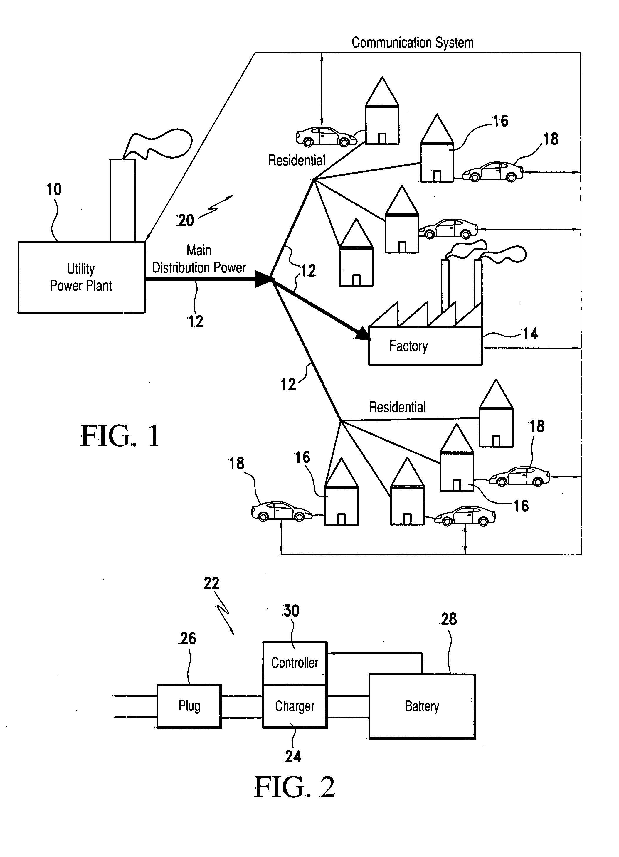
[0026]Turning first to FIG. 1, an electric utility power plant 10 distributes power on a grid 12 to its customers located at factories 14, commercial facilities and homes 16, where some utility customers recharge batteries of electric vehicles including PHEVs 18. A communication system 20 linking the customers and the utility 10 carries bidirectional transmissions to and from battery charging systems 22 located on board each PHEV 18.

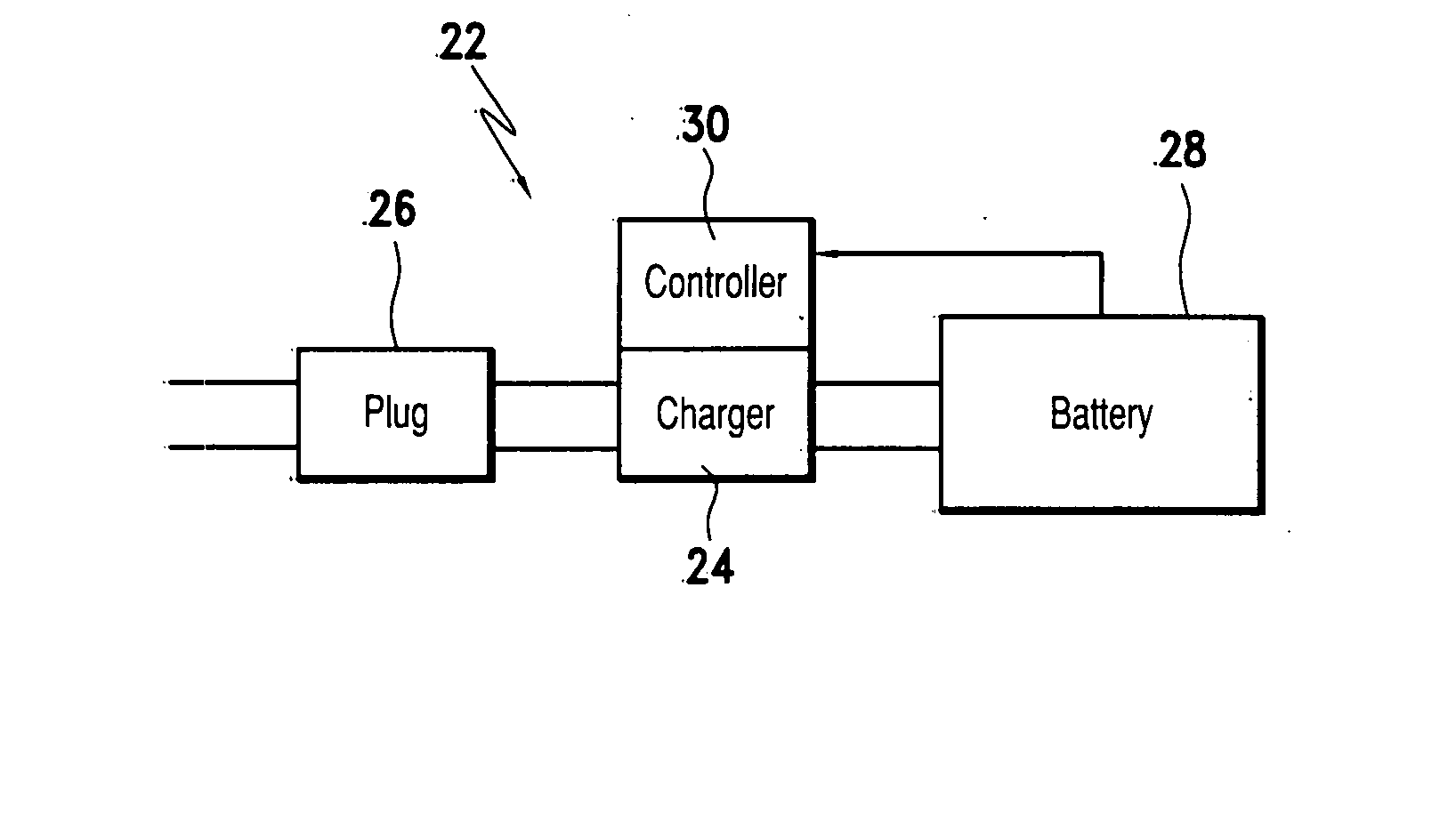
[0027]The PHEV battery charging system 22 shown in FIG. 2 includes a plug-in charger 24, equipped with plugs adapted for insertion into a conventional electrical receptacle 26 connected to the power grid 12, an electric storage battery 28, and a controller 30 electrically connecting the charger 24 and battery 28 and communicating bi-directionally through the charger with the electric utility 10. Controller 30 continually monitors the current state of charge (SOC) of the onboard electric storage battery 28, has access to electronic memory containing a max...


PUM


Abstract

A method for recharging an electric storage battery in the charging system of an electric vehicle from an electric utility power grid includes determining the length of time required to recharge the battery, determining the desired time when the recharge is to be completed, transmitting to the electric power utility the length of time required to recharge the battery and the desired time, and recharging the battery from the utility grid during a period when projected load demand is lower than peak demand and ending no later than the desired time.

Description

BACKGROUND OF THE INVENTION[0001]1. Field of the Invention[0002]The preferred embodiment relates generally to a system and method for recharging an electric storage battery located onboard a vehicle driven at least in part by electric energy.[0003]2. Description of the Prior Art[0004]A hybrid vehicle is a vehicle that uses two distinct power sources, such as an on-board rechargeable energy storage system and a fueled power source for vehicle propulsion. The term hybrid vehicle most commonly refers to hybrid-electric vehicle (HEV), which use internal combustion engines and electric batteries to power electric motors. Generally, kinetic energy of the vehicle is recovered during braking, converted to electric energy and stored in one of the batteries.[0005]A plug-in hybrid electric vehicle (PHEV) is a hybrid, which has additional battery capacity and the ability to be recharged from an external electrical outlet supplied by a public utility power grid. The vehicle can be used for short...

Claims


Application Information

Patent Timeline
Patent Type & Authority Applications(United States)
IPC IPC(8): H02J7/16H02J7/04B60L50/15
CPCB60L11/1816Y02E60/721B60L11/184B60L11/1844Y02T10/6269Y02T10/7005Y02T90/121Y02T90/128Y02T90/14Y02T90/163Y10S903/907Y02T90/169Y04S10/126Y04S30/14B60L11/1824Y02T10/7072B60L53/14B60L53/64B60L53/63B60L53/305Y02E60/00Y02T10/62Y02T10/70Y02T90/12Y02T90/167Y02T90/16B60L50/15B60K6/20B60W20/00
Inventor GALE, ALLAN R.DEGNER, MICHAEL W.
Owner FORD GLOBAL TECH LLC
Why Eureka
Try Eureka