
Cold weather equipment box

a technology for equipment boxes and cold weather, applied in the field of equipment boxes, can solve the problems of reducing the power capacity of all such battery power sources, requiring careful handling, and all described electrical devices, whether electric or gas powered, and achieve the effects of convenient moving a fish finder, preserving battery energy capacity, and ensuring safety

Inactive Publication Date: 2008-08-28
ANDREWS AARON C
View PDF19 Cites 11 Cited by
  • Summary
  • Abstract
  • Description
  • Claims
  • Application Information

AI Technical Summary

Benefits of technology

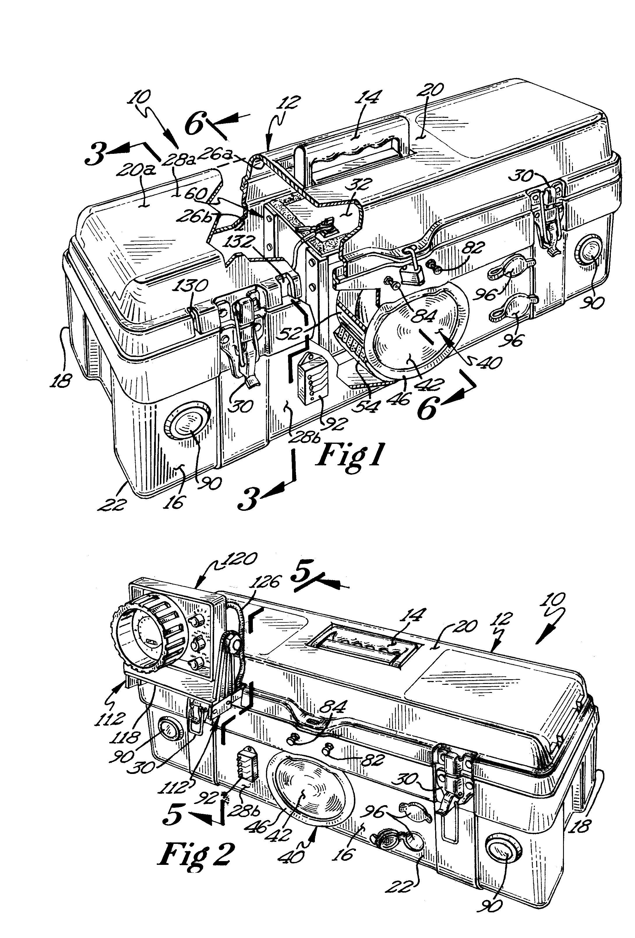
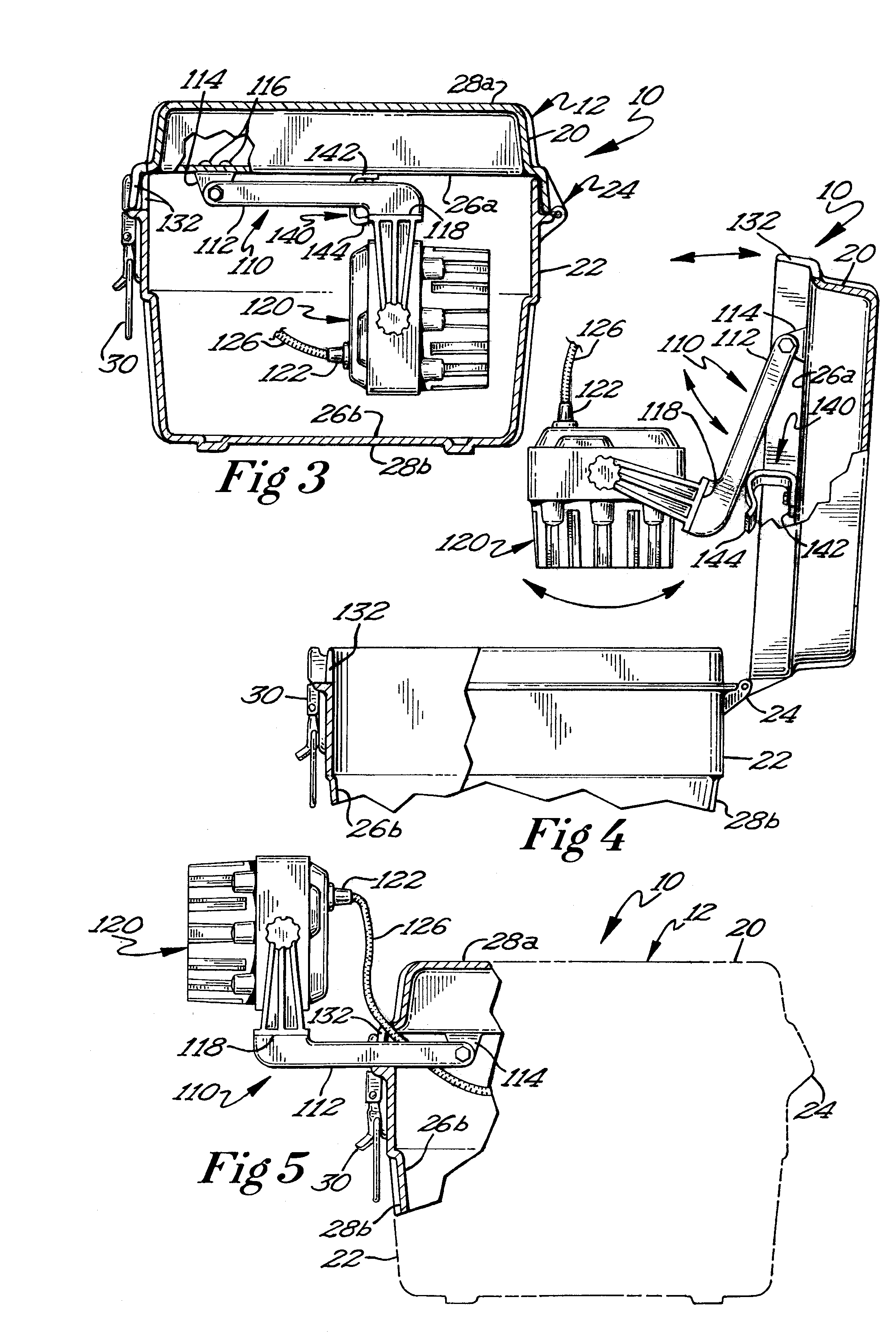
[0011]The preferred equipment box of the present invention further includes an accessory mount for safely, conveniently moving a fish finder between a safe storage position within the box and an operating position external to the box. The accessory mount is preferably rotatably fastened to the tackle box, which is arranged and configured such that the fish finder may be positioned outside of the box in the operating position even when the box lid is closed. This provides numerous advantages as the fish finder may be used even while the box is being moved about, and since the box lid is closed, the battery will remain better insulated and protected from the elements during all such movement.
[0012]It is an object of the present invention to provide an equipment box that adequately powers and stores multiple battery operated devices. It is another object of the present invention to provide an equipment box that maintains battery energy capacity for a longer time intervals during frigid conditions, such as those associated with ice fishing. It is a further object of the present invention to provide an equipment box that uses otherwise wasted heat energy produced by a heat generating light bulb to maintain an effective working temperature for the battery.

Problems solved by technology

All these devices require sources of battery power, and all such battery power sources experience diminished power capabilities when used outdoors under low temperature conditions.
In addition to the described electrical power difficulties, all the described electrical devices are somewhat fragile, and carrying them to the fishing site without damaging them presents a further challenge.
Similarly, lighting devices, whether electric or gas powered, are somewhat fragile and require careful handling during transport to the ice fishing site.
All of these described accessories, devices and containers are burdensome to transport since, as the name implies, ice fishing is done on a sheet of ice usually distant from the shore of a lake or river and far from the fisherman's vehicle.
While various transport carts and containers have been developed for ice fishing use, there is no known single container or transport mechanism which allows multiple electrical and fishing accessories to be protectively housed and transported and a storage battery power source effectively protected from the frigid temperatures which can substantially diminish its electrical capacity.
While the McPhaul device is an effective lighting device for warm season fishing, McPhaul discloses no features for addressing the more extreme cold temperature conditions of ice fishing or to protecting a battery from the cold.
The known equipment boxes are not well adapted for protecting a battery for prolonged use in the frigid conditions, such as those conditions associated with ice fishing.
The known equipment boxes provide no adequate insulation mechanism to insulate a battery power source from the ambient cold and no mechanism to generate, capture, or apply heat to the battery power source.
Consequently the battery used in a tackle box like that of McPhaul quickly cools to outdoor temperatures and the electrical output capacity of the battery diminishes significantly.
As batteries cool down and eventually even freeze, they quickly reach a point where they cannot deliver enough power to keep up with the larger demand needed by the more numerous electrical devices now used.

Method used


Image

  • Cold weather equipment box
  • Cold weather equipment box
  • Cold weather equipment box

Examples


Embodiment Construction

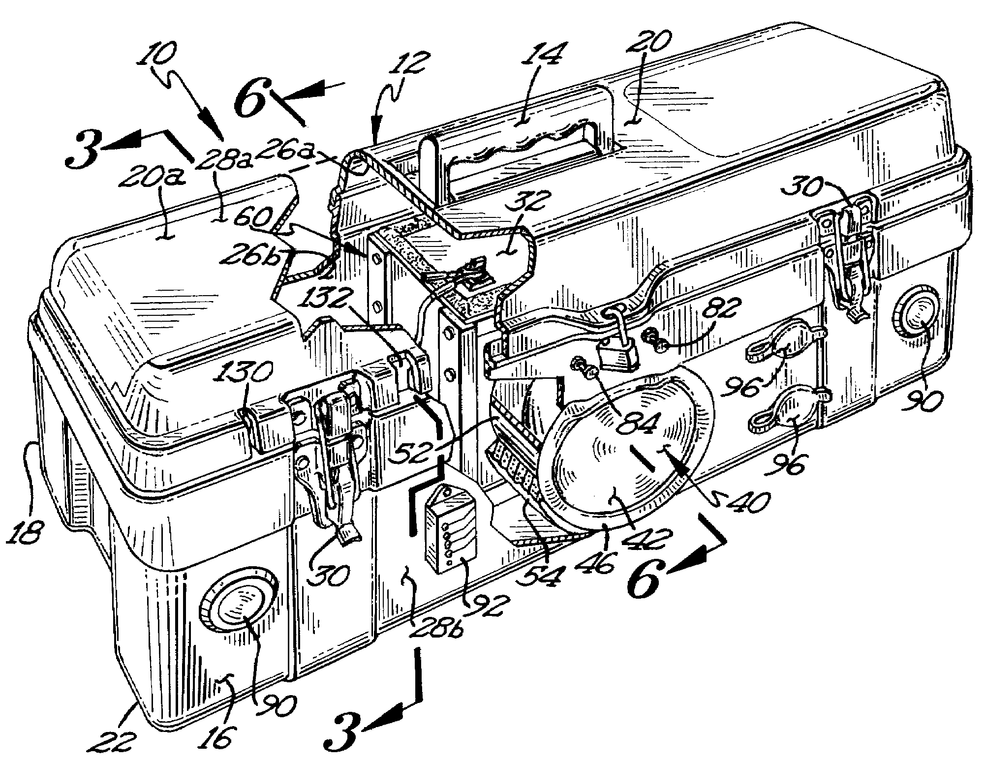
[0022]Referring now to FIG. 1, an embodiment 10 of a cold weather equipment box here shown as an ice fishing tackle box includes a generally hollow, rigid housing 12 preferably having a carrying handle 14, a front 16, a back 18, a top portion 20 and a bottom portion 22 interconnected by at least one hinge 24, each portion 20, 22 having an interior surface 26a, 26b respectively, and an exterior surface 28a, 28b respectively. FIG. 1 shows the housing 12 in a closed position wherein the lid 20a of top portion 20 lies flush against the bottom portion 22. Preferably at least one latch 30 is provided such that the top portion 20 can be releasably secured to the bottom portion 22.

[0023]The embodiment 10 of the ice fishing tackle box of the present invention further includes a heat generating light source, here shown as bulb or lamp 40, preferably an incandescent light bulb of about 30 watts, secured to the bottom portion 22. The heat generating light source 40 has a transparent front cover...


PUM


Abstract

An equipment box, particularly useful for ice fishing, capable of powering multiple electrical and electronic devices. The equipment box includes a heat generating light source and a housing having a top portion, a bottom portion and a battery enclosure within the bottom portion that accommodates a battery to power the light source. Otherwise wasted heat energy produced by the light source is directed to the battery via a heat channel to warm the battery, thus prolonging battery life and capacity in cold conditions. The enclosure may include a separate layer of insulation as well as a liner positioned between the insulation and the battery so that the battery can be easily removed from the enclosure. The equipment box preferably includes an accessory mount that allows a fish finder to moved between a storage position located within the housing and an operating position located outside the housing.

Description

BACKGROUND OF THE DISCLOSURE[0001]1. Field of the Invention[0002]The present invention relates generally to equipment boxes used for cold weather work or sport activity. Particularly, the present invention relates to equipment boxes for use in low light, frigid, ice fishing conditions, where reliable battery power is needed by a user for the operation of multiple electric devices such as light sources, mobile phone, a fish finder, radio and the like.[0003]2. Description of the Related Art[0004]Known fishing equipment boxes have a storage housing covered by a lid, the housing having various compartments and trays to store fishing gear such as line, hooks, lures and the like. It is now a common practice in ice fishing to use battery powered devices while fishing, for example, light sources due to shortened winter days and the preference for dawn or dusk fishing, mobile phones, radios and portable music devices for safety and enjoyment, and fish finders for ease of site location. All t...

Claims


Application Information

Patent Timeline
Patent Type & Authority Applications(United States)
IPC IPC(8): A45C15/06F21V29/00
CPCA45C5/00A45C11/20A45C15/00A45C15/06F21V29/15F21V21/30F21V29/004F21V33/008H01M2/1066F21S9/02F21Y2115/10F21V29/83Y02E60/10
Inventor ANDREWS, AARON C.
Owner ANDREWS AARON C
Learn More