Light emitting device

a light emitting device and light technology, applied in semiconductor lasers, instruments, applications, etc., can solve the problems of shortening the life of the light emitting device, unable to achieve satisfactory levels of both light emitting efficiency and color rendering properties, and insufficient color rendering properties, etc., to achieve excellent color rendering properties for color reproduction, good light emitting efficiency, and linear spectrum

Active Publication Date: 2008-08-28
NICHIA CORP
View PDF10 Cites 86 Cited by
  • Summary
  • Abstract
  • Description
  • Claims
  • Application Information

AI Technical Summary

Benefits of technology

[0016]An object of the present invention is to provide a light emitting device which can achieve excellent color rendering properties for color reproduction using a semiconductor laser which emits blue wavelength light with good light emitting efficiency and which has a linear spectrum in the blue wavelength band.
[0017]Furthermore, from another viewpoint, a further object is to provide a high-performance light emitting device which satisfies both properties of the mutual trade-off relationship between high color rendering properties and good light emitting efficiency which emits light at extremely high brightness.
[0018]Furthermore, from yet another viewpoint, another object is to prevent degradation of the materials which form the light emitting device using semiconductor light emitting elements with good light emitting efficiency, and to provide a light emitting device with long life.
[0021]Using the light emitting device of the present invention, excellent color rendering properties can be shown by using a combination of laser elements which radiate very bright excitation light in the blue wavelength band together with another laser element.

Problems solved by technology

In particular, sufficient color rendering properties cannot be sufficiently achieved when using a semiconductor laser which emits blue wavelength light because of the unique properties of this laser, namely the property of having a linear spectrum in the blue wavelength band and having extremely low light emitting intensity across a relatively wide band of adjacent wavelength bands (such as near ultraviolet bands and blue-green wavelength bands).
In addition, extremely high brightness may be required depending on the use of the light source device, but there is a mutual trade-off relationship between light emitting efficiency / brightness and color rendering properties, and sufficiently achieving satisfactory levels of both light emitting efficiency and color rendering properties is difficult.
Note that semiconductor light emitting elements such as semiconductor lasers are required to have even higher brightness and high light emitting efficiency, but the light density is generally high, so the resins and the fluorescent material or the like which make up the wavelength converting member will be heated and degraded by the high density excitation light, thus leading to a shorter life for the light emitting device.

Method used


Image

  • Light emitting device
  • Light emitting device
  • Light emitting device

Examples


embodiment 1

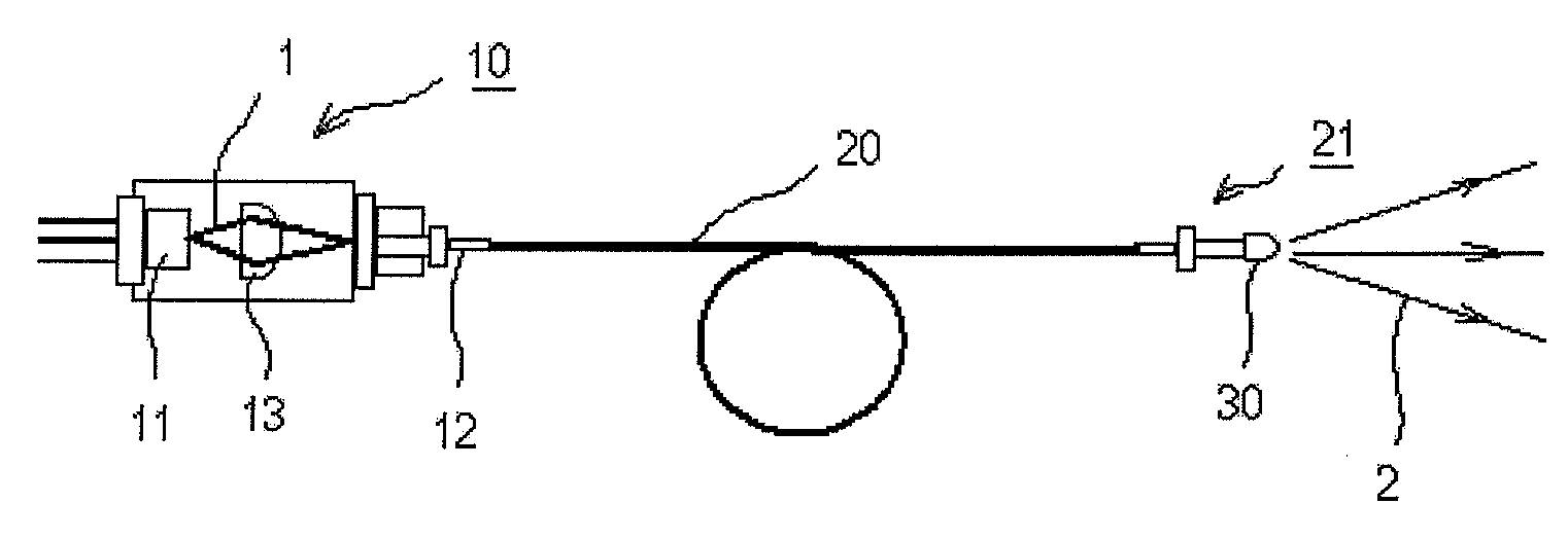
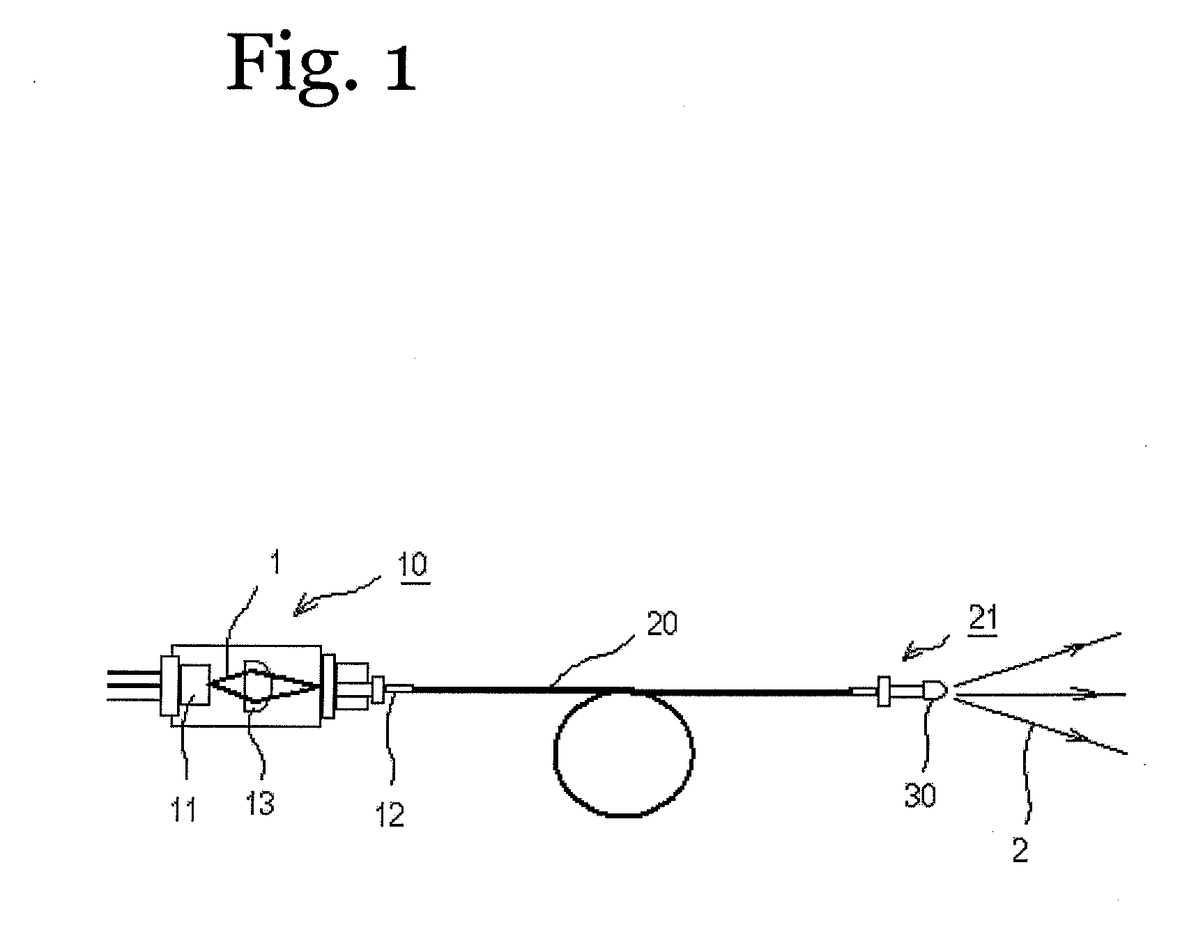
[0206]As shown in FIG. 1, the light emitting device of this embodiment is constructed by combining two units each comprising an excitation light source 10, a light guide 20, and a wavelength converting member 30.

[0207]The first unit uses a blue laser element 11 with a GaN semiconductor which has an emission peak wavelength around 445 nm as the excitation light source 10. A lens 13 for collecting the excitation light 1 from the laser element is located in front of the laser element.

[0208]The light guide 20 is connected on one end to the light radiating part 12 of the excitation light source 10, and connected on the other end to the output unit 21. The light guide 20 is made from quartz and for instance has Si 114 (μm: core diameter) / 125 (μm: clad diameter).

[0209]The wavelength converting member 30 was molded to uniformly disperse the fluorescent material throughout the resin, and is attached to the output unit 21.

[0210]The fluorescent material was made by mixing 0.54 g of (Lu, Ce)3Al...

embodiment 2

[0218]A light emitting device of this embodiment was produced essentially identical to the device of the first embodiment except that SCESN was replaced with SESN in both the first and second units.

[0219]When evaluated similar to the first embodiment, essentially the same results for color rendering properties and light emitting efficiency were obtained.

embodiment 3

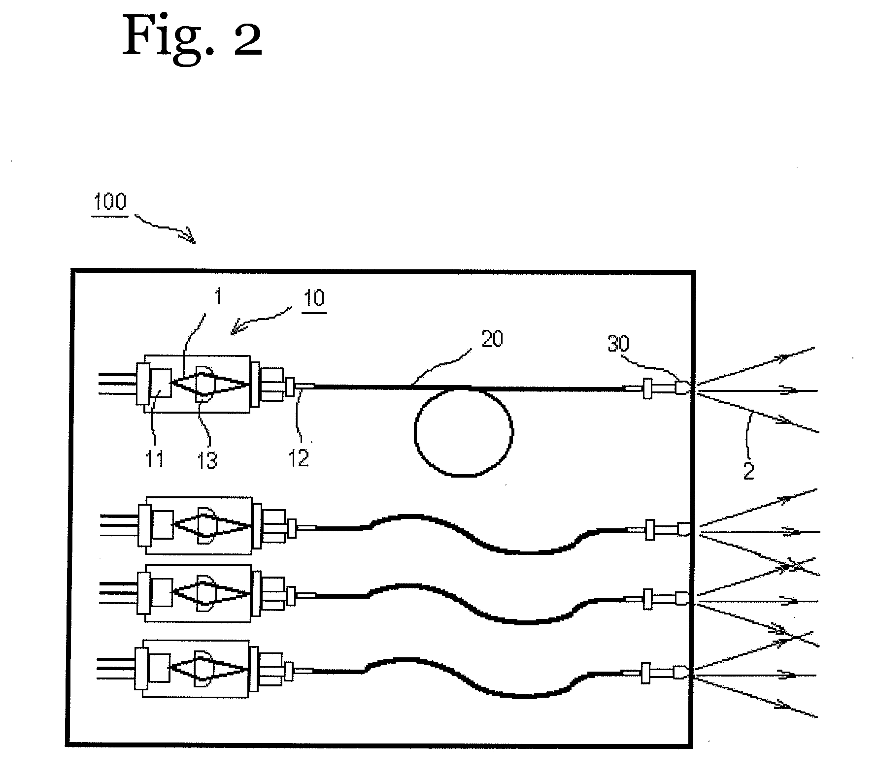
[0220]As shown in FIG. 10, a light source device with high color rendering properties of Ra=80, good linearity and high light emitting efficiency could be obtained using this light emitting device by combining five of the first units 42 (excitation wavelength 445 nm) obtained in the first embodiment and three of the second units 41 (excitation wavelength 405 nm) using a bundle fiber 40.


PUM


Abstract

A light emitting device includes a first unit having a first excitation light source including a laser element emitting blue wavelength band excitation light, and a first wavelength converting member including at least one type of fluorescent material and which absorbs at least a portion of a first excitation light, converts the wavelength, and releases light with a wavelength longer than the first excitation light, and a second unit having a second excitation light source including a laser element which emits excitation light with a wavelength band shorter than the blue wavelength band excitation light, and a second wavelength converting member which includes at least one type of fluorescent material and which absorbs at least a portion of a second excitation light, converts the wavelength, and releases light with a wavelength longer than the second excitation light. The first unit and the second unit are combined using a bundle fiber.

Description

CROSS-REFERENCE TO RELATED APPLICATIONS[0001]This application is a continuation application of U.S. patent application Ser. No. 11 / 302,469 filed on Dec. 14, 2005. This application claims priority to Japanese Patent Application Nos. 2004-363103 and 2004-366646. The entire disclosures of U.S. patent application Ser. No. 11 / 302,469, Japanese Patent Application Nos. 2004-363103 and 2004-366646 are hereby incorporated herein by reference.BACKGROUND OF THE INVENTION[0002]1. Field of the Invention[0003]The present invention relates to a light emitting device, and more particularly relates to light emitting device which has an excitation light source, a wavelength converting member, and a light guide.[0004]2. Background Information[0005]Conventionally, endoscope devices for in vivo observations and for performing treatment during observations, and fiber scopes for observing in extremely narrow or extremely dark spaces have been widely used.[0006]Endoscopes and fiber scopes are constructed w...

Claims


Application Information

Patent Timeline
Patent Type & Authority Applications(United States)
IPC IPC(8): H01S3/08
CPCA61B1/0017A61B1/063A61B1/0638A61B1/0653A61B1/07H01S5/4025G02B6/262G02B23/2469G02B2207/113H01S5/005H01S5/02284G02B6/14H01S5/02251H01S5/0087H01S5/0085
Inventor HAMA, ATSUTOMONAGAHAMA, SHINICHIHAYASHI, YUKIHIRO
Owner NICHIA CORP
Why Eureka
Try Eureka