
Matching Apparatus, Image Search System, and Histogram Approximate Restoring Unit, and Matching Method, Image Search Method, and Histogram Approximate Restoring Method

a technology of image search and matching method, applied in the field of matching method, image search method, and histogram approximate restoration method, can solve the problems of not being able to meet the requirement of fast processing and complicated calculation processing, and achieve the effect of efficiently restoring the original image pixel value histogram, easy calculation processing of object matching, and fast object matching

Inactive Publication Date: 2008-08-28
KITAKYUSHU FOUND FOR THE ADVANCEMENT OF IND +1
View PDF3 Cites 18 Cited by
  • Summary
  • Abstract
  • Description
  • Claims
  • Application Information

AI Technical Summary

Benefits of technology

[0115]As mentioned above, according to the present invention, a plurality of feature points projected on the multi-dimensional space are mapped on the one-dimensional space. The similarity between two objects on the one-dimensional space is determined on the basis of the distance between the feature points of the two objects. As a consequence, advantageously, the calculation processing of object matching is easy and the object matching is fast.
[0116]Further, according to the present invention, pixels are distributed so that pixels approximate to a discrete pixel value histogram of image data encoded compressed

Problems solved by technology

However, if increasing the number of feature points and the number of dimensions, the calculation processing becomes complicated and this cannot respond to the requirement of the fast processing.

Method used


Image

  • Matching Apparatus, Image Search System, and Histogram Approximate Restoring Unit, and Matching Method, Image Search Method, and Histogram Approximate Restoring Method
  • Matching Apparatus, Image Search System, and Histogram Approximate Restoring Unit, and Matching Method, Image Search Method, and Histogram Approximate Restoring Method
  • Matching Apparatus, Image Search System, and Histogram Approximate Restoring Unit, and Matching Method, Image Search Method, and Histogram Approximate Restoring Method

Examples


first embodiment

[0182]According to the first embodiment, an example of applying a matching apparatus according to the present invention to image matching will be described.

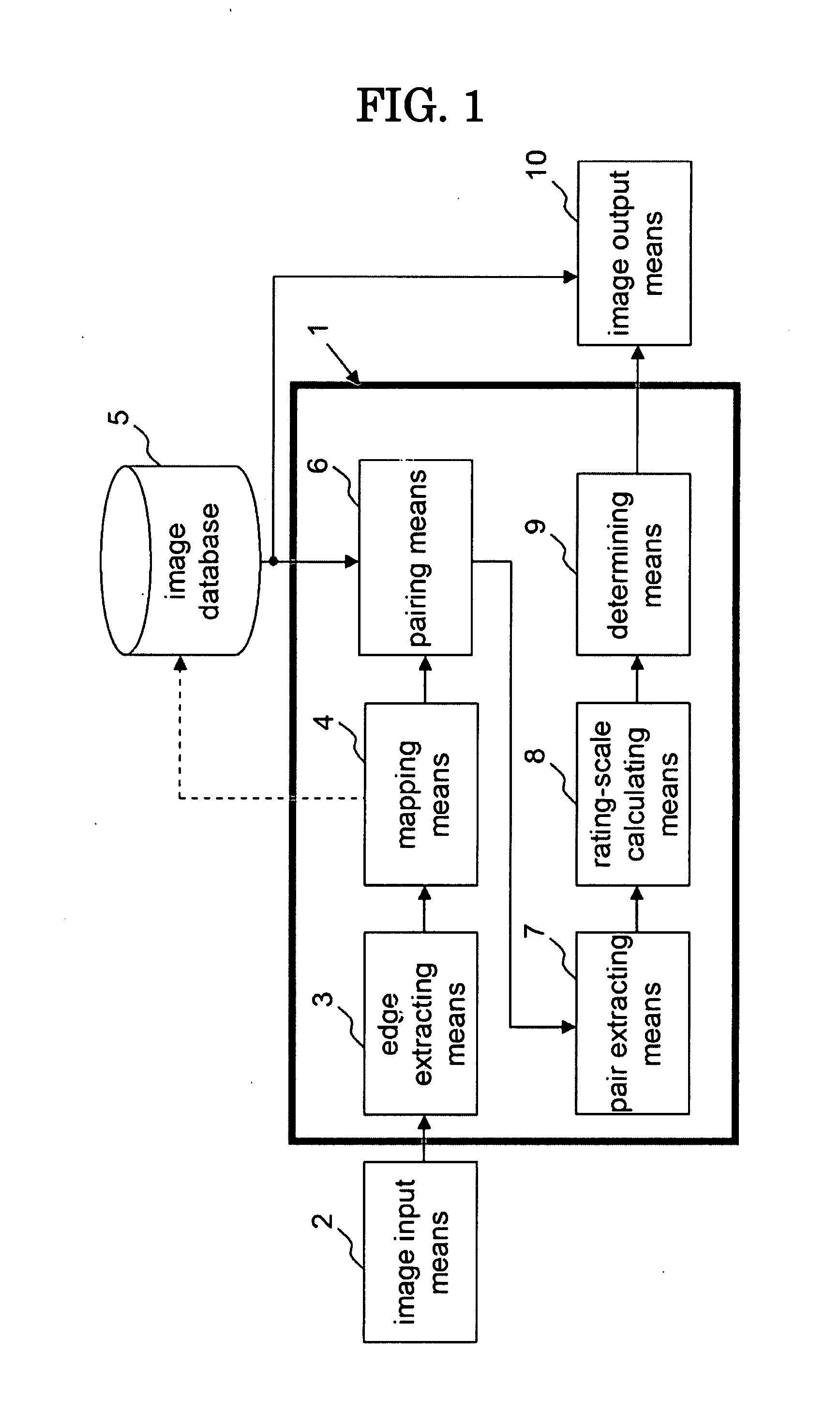
[0183]FIG. 1 is a block diagram showing the functional structure of an image search apparatus using a matching apparatus 1 according to the first embodiment of the present invention.

[0184]The image search apparatus according to the first embodiment comprises: the matching apparatus 1; image input means 2; an image database (hereinafter, referred to as an “image DB”) 5; and image output means 10.

[0185]The image input means 2 is an interface for inputting a query image serving as a reference object or a data image serving as a compared object. The query image is directly input from image pickup means such as a digital camera and has an input form for selecting the input from a recording medium and the input from another information device via a communication line. Further, the image input means 2 is used for inputting the data imag...

second embodiment

[0221]According to the second embodiment, only the calculation of the rating scale is different from the first embodiment, and another structure and operation of the matching apparatus 1 are substantially similar to that according to the first embodiment.

[0222]The second embodiment uses, as the rating scale, Hirbert scanning distance (HSD) dHSD, which will be defined later.

[0223][Definition 1] (Hirbert Scanning Distance)

[0224]A reference image A and a compared image B are bijected on the one-dimensional space with Hirbert scanning, and data elements (pixels) thereof are thus designated by uj (j=1, 2, . . . , N) and vk (k=1, 2, . . . , N′). At this time, dHSD expressed by the following expression (4) is referred to as Hirbert scanning distance.

[Expression5]dHSD=1N∑i=1Nρ(minkuj-vk)(4)

[0225]Herein, a function ρ is defined by the following expression (5). Reference numeral τ denotes a threshold (constant).

[Expression6]ρ(x)={x(x≤τ)τ(x>τ)(5)

[0226](End of Definition)

[0227]FIG. 7 is a bl...

example 1

[0238]In order to evaluate the robustness to noise and the precision of the matching apparatus according to the second embodiment, an image shown in FIG. 9(a) is used as an original image. A part of the original is cut-off and the query image shown in FIG. 9(b) is created. The size of the original image is 512×256 pixels, and the size of the query image is 128×128 pixels. The best matching position of the query image in the original image is (28, 119) (Incidentally, the origin of the coordinate system is expressed as the coordinate of the upper-left vertex, and the position of the query image is expressed as the coordinate of the upper-left vertex of the query image).

[0239]In order to evaluate the precision of the matching processing, the original image shown in FIG. 9(a) is set as a data image A, and the data image A is compared with the query image. Further, in order to evaluate the robustness to the noise of the matching processing, images B to G obtained by adding the noise to t...


PUM


Abstract

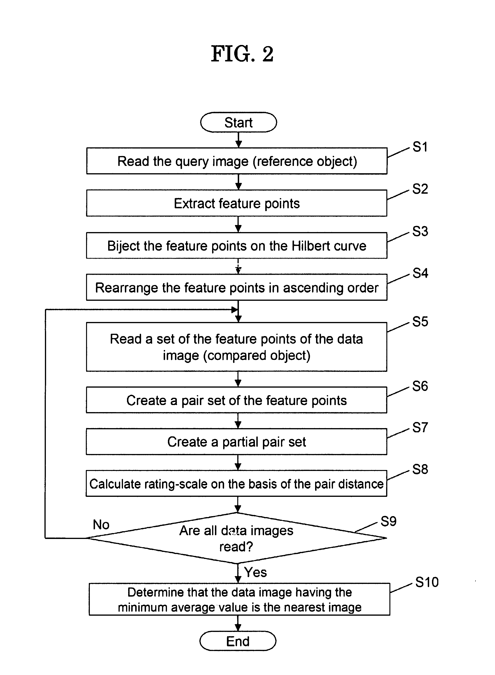
To provide a matching technology for determining the similarity between two objects at high velocity with high precision.A matching method for comparing a set of feature points of two objects projected to an N-dimensional space and determining the similarity between the two objects, includes a mapping step (S3) of mapping the set to a one-dimensional space, a pairing step (S6) of creating a set of pairs of a feature point of first object that is the most approximate to a feature point of second object, a partial-set creating step (S7) of partly extracting the pairs in small order of the pair distance from the set of the pairs of the feature points and creating a partial set of the pairs of the feature points, an average-value calculating step (S8) of calculating a rating-scale of the pair belonging to the partial set of the pair of the feature points, and a determining step (S10) of determining the similarity between the first object and the second object on the basis of an average value of the distance.

Description

TECHNICAL FIELD[0001]The present invention relates to a matching technology for determining the similarity of two objects and an image search technology applying it.BACKGROUND ART[0002]Data having a common purpose is called an “object”. In general, the object comprises a large number of pieces of data, e.g., a still image, a motion image, sound, and a document. In an information search field, such a matching technology is greatly important that two objects are compared with each other and the similarity therebetween is compared and is determined. The matching technology is applied to various fields including an image search, speech search, and document search.[0003]As a conventional matching technology, e.g., technologies disclosed in Patent Documents 1 to 4 are well-known.[0004]According to a matching method disclosed in Patent Document 1, a set of all feature points of one image is compared with a set of all feature points of another image and, then, when both the sets are similar...

Claims


Application Information

Patent Timeline
IPC IPC(8): G06K9/34G06K9/46G06V10/50
CPCG06K9/6202G06K9/4642G06V10/50G06V10/751
Inventor KAMATA, SEIICHIROTSUNEYCSHI, KAZUYU
Owner KITAKYUSHU FOUND FOR THE ADVANCEMENT OF IND
Learn More