

Plasmid DNA isolation
a technology of plasmid dna and plasmid cDNA, which is applied in the field of plasmid cDNA isolation, can solve the problems of inefficiency, time-consuming, tedious, etc., and achieve the effect of improving the recovery rate, reducing the cost of treatment, and improving the recovery ra
- Summary
- Abstract
- Description
- Claims
- Application Information
AI Technical Summary
Benefits of technology
Problems solved by technology
Method used
Image

Examples
Embodiment Construction
[0038]This invention provides methods, apparatus and reagents for rapidly isolating plasmid and similar epimeric forms of DNA from bacteria.
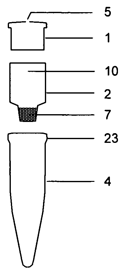
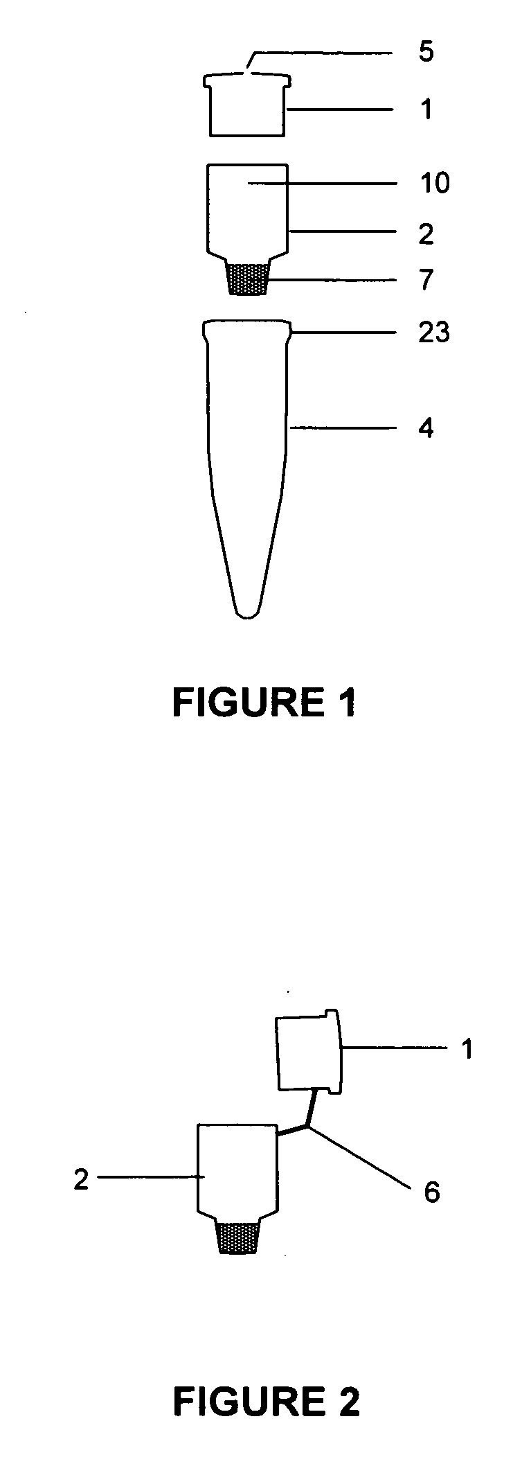
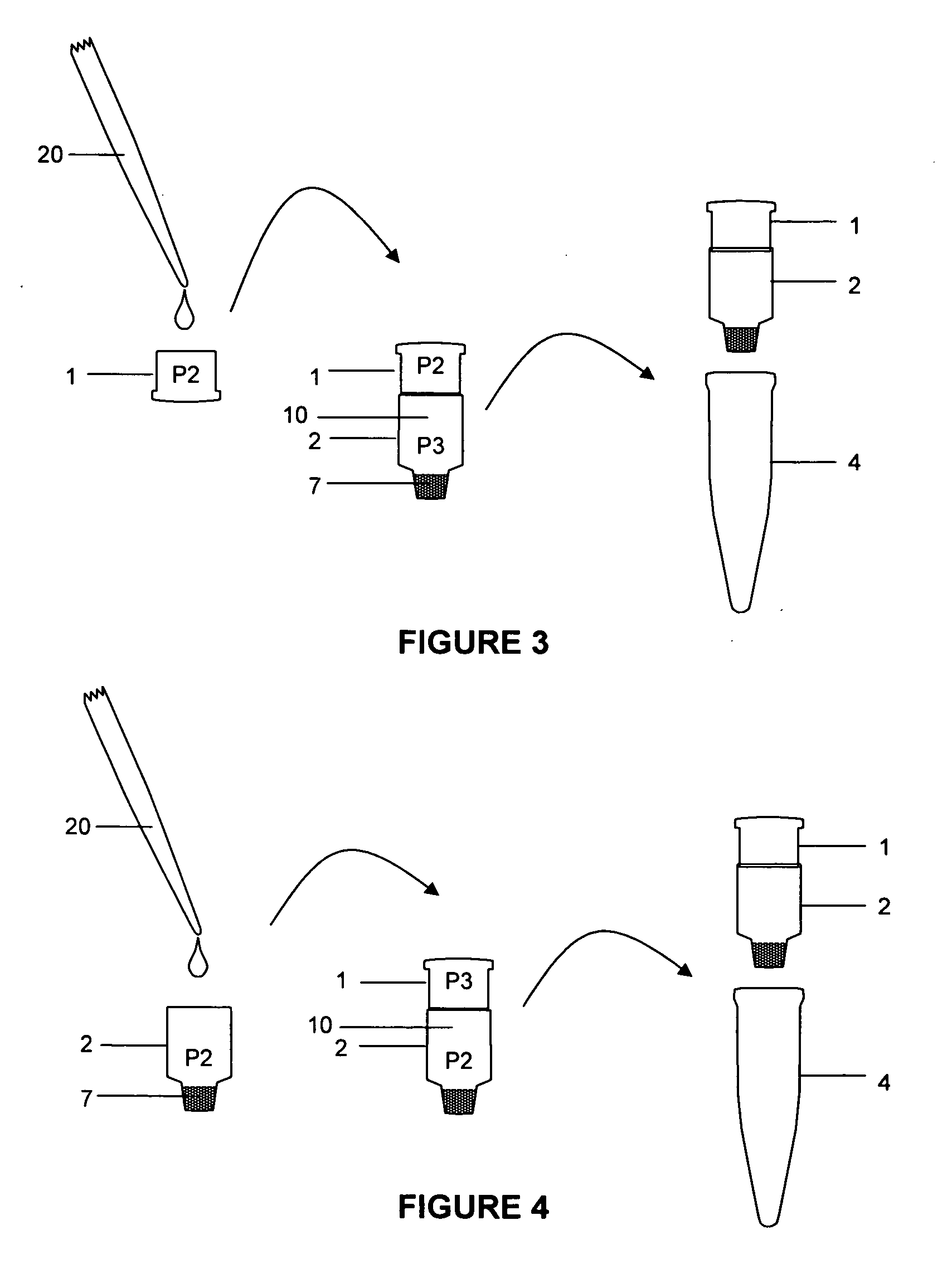
[0039]In one embodiment, the invention utilizes a lysate filtration device for filtering precipitated material (i.e., proteins and genomic DNA complexes) from a bacterial alkaline lysate prepared directly from a bacterial culture, without first performing the separate procedures of concentrating the bacteria, denaturing the plasmid and bacterial genomic DNA using a strong base, and then neutralizing the resulting solution with acid. These separate steps are conventionally performing using three aqueous solutions, i.e., resuspension buffer, lysis buffer, and neutralization buffer, often abbreviated P1, P2, and P3, respectively.
[0040]An important feature of the present invention is that the lysate filtration device comprises at least one solid or immobilized alkaline lysis reagent (i.e., P2 and / or P3), which dissolves or is released upon contact w...
PUM
| Property | Measurement | Unit |
|---|---|---|
| volume | aaaaa | aaaaa |
| volume | aaaaa | aaaaa |
| water-soluble | aaaaa | aaaaa |
Abstract
Description
Claims
Application Information