
Wireless body sensor with small size background

a sensor and small size technology, applied in the field of small size wireless body sensors, can solve the problems of inapplicability of wearable signal processing devices, individual sensors span too large physical distances to be located on a single wearable device, etc., and achieve the effect of greatly reducing interference and nois

Inactive Publication Date: 2008-08-28
MICROSOFT TECH LICENSING LLC
View PDF4 Cites 11 Cited by
  • Summary
  • Abstract
  • Description
  • Claims
  • Application Information

AI Technical Summary

Benefits of technology

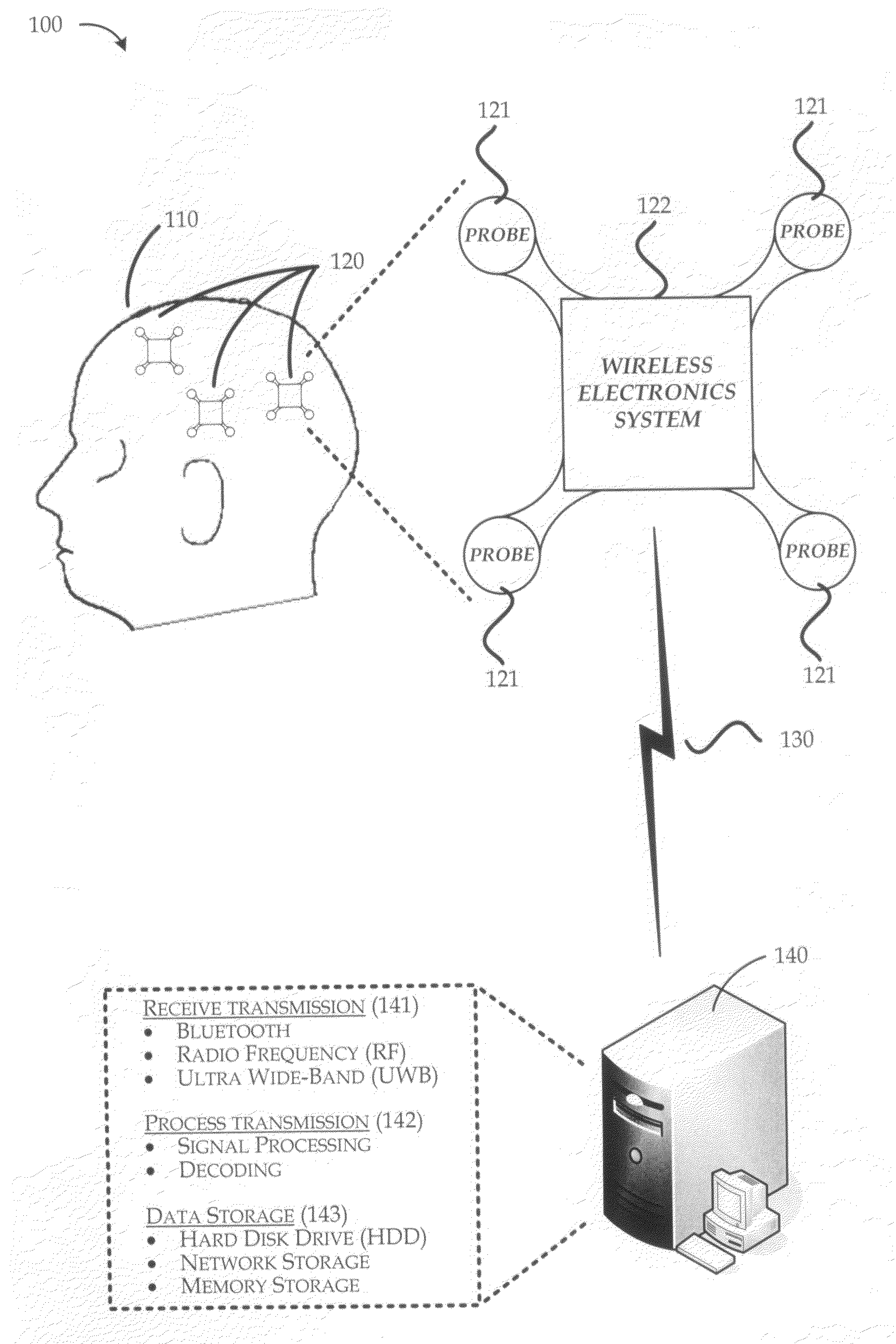
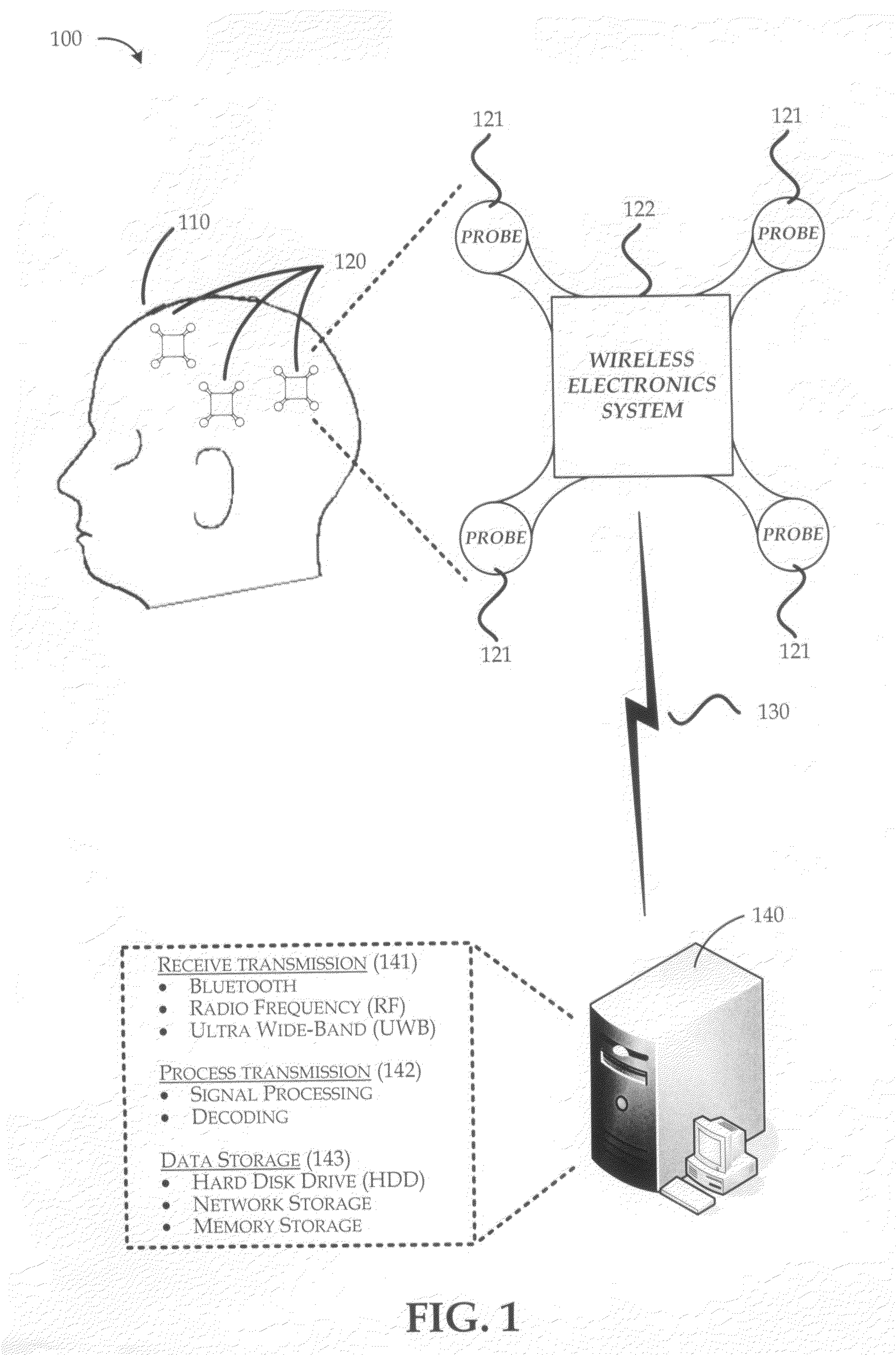
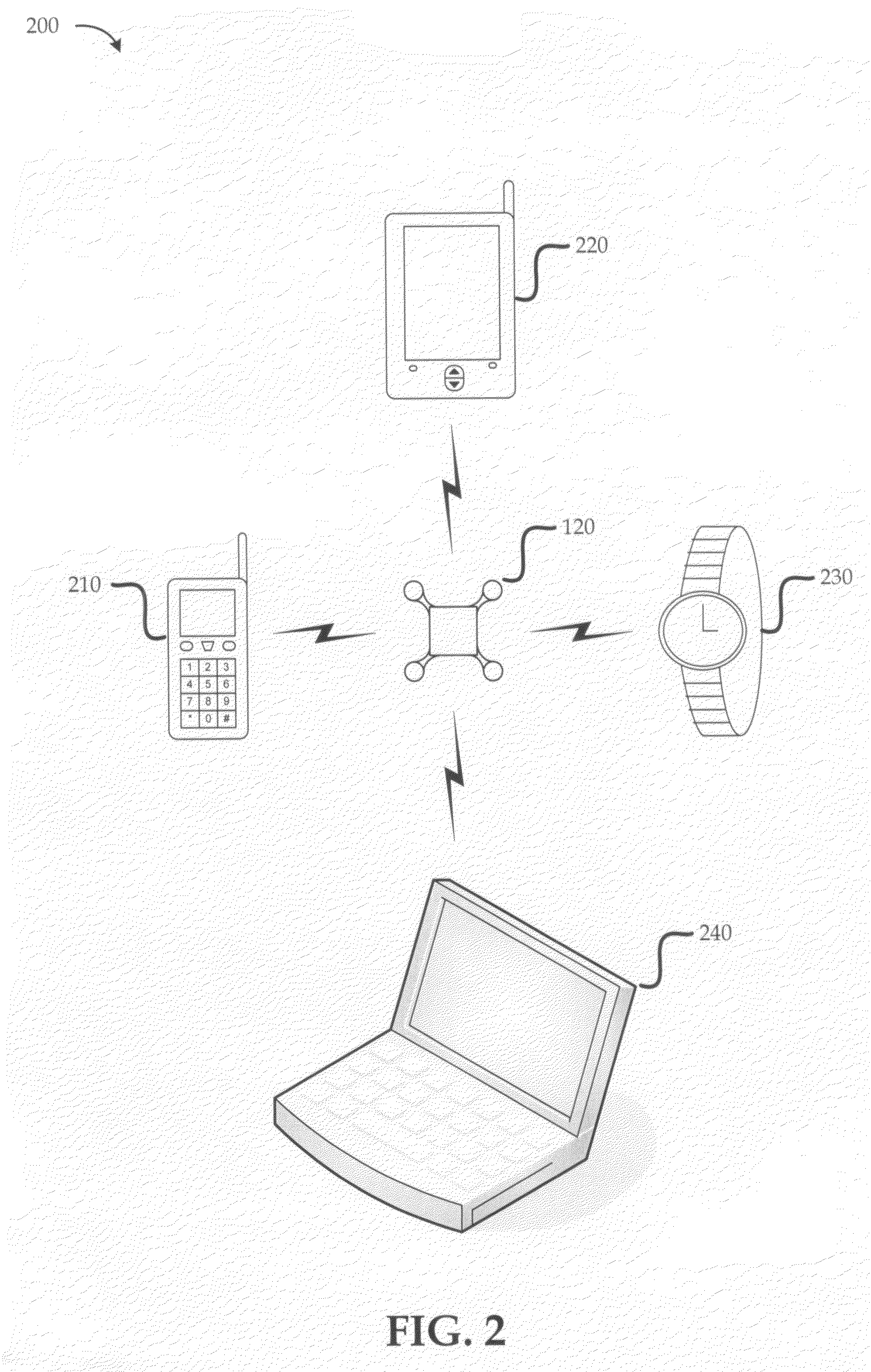
[0007]The present disclosure is related to devices, methods and systems for sensing and processing bio-potentials. A wireless body sensor device includes a number of small probes that are arranged about a wireless electronics system. The wireless electronics system can process bio-potential signals from the probes and communicate bio-potential data to another device such as a wireless telephone, wrist watch, personal data assistant (PDA), laptop computer or any other appropriate device. By forming the probes within a confined short range of the wireless electronics system, interference and noise is greatly reduced. An array of the wireless body sensor devices can be mapped into a Cartesian coordinate system for recording a multiplicity of readings that can later be mapped into familiar representations such as an EEG or other bio-potential measurement system that is known to health care workers.

Problems solved by technology

In one example, the individual sensors span too great a physical distance to be located on a single wearable device.
In another example, the sensors are physically located in places where a wearable signal processing device is not practical.

Method used


Image

  • Wireless body sensor with small size background
  • Wireless body sensor with small size background
  • Wireless body sensor with small size background

Examples


examples process

Flows

[0051]Once bio-potentials are processed and sampled, the bio-potential data needs to be transmitted to a device that can either process, log or display the results. The bio-potential data can be transmitted directly to a personal computer or to another computing device such as a wristwatch, cell phone or some other mobile computing device as previously described.

[0052]FIG. 7 is a flow diagram (700) illustrating an implementation of a method employed by a wireless body sensor device to process and transmit bio-potentials in accordance with the present disclosure. Processing begins at block 701, and proceeds to block 702 where the bio-potential probes sense various potentials. At block 703, the MEMS switch array can optionally provide auto-zero functions to the inputs of the signal amplifiers. Continuing at block 704, the signals from the bio-potential probes are coupled to the signal amplifiers and produce amplified signals. At block 705, the amplified signals are converted into...


PUM


Abstract

A wireless body sensor device includes a number of small probes that are arranged about a wireless electronics system. The wireless electronics system can process bio-potential signals from the probes and communicate bio-potential data to another device such as a wireless telephone, wrist watch, personal data assistant (PDA), laptop computer or any other appropriate device. By forming the probes within a confined short range of the wireless electronics system, interference and noise is greatly reduced. The wireless electronics system includes signal amplifiers that increase the signal levels associated with the bio-potential probes so that the signals can be converted to bio-potential data through an analog-to-digital conversion (ADC) process. Once the bio-potential data is in digital form, the data can be processed by a digital signal processor (DSP), encoded into a signal transmission, and communicated to another device with a radio system and its corresponding antenna.

Description

BACKGROUND[0001]Body sensor systems are currently used for in health diagnostics and in health maintenance applications. Example applications for body sensor systems include: monitoring sports performance, diagnosing metabolic disorders, identifying sleep disorders, as well as monitoring specific body systems cardiac and neurological systems.[0002]Some example body sensor systems are used for processing simple physiological data, while other body sensor systems are used for processing bio-potential data. Simple physiological data includes measurements for physiological characteristics such as blood pressure, heart rate, skin temperature, and body temperature, to name a few. On the other hand, bio-potential data is a measurement of differences in potential between two points of interest on the body. Bio-potential data is often associated with measurements such as electro-cardiograms (ECG / EKG), where the electrical voltages for heart activity are monitored, electro-encephalograms (EEG...

Claims


Application Information

Patent Timeline
Patent Type & Authority Applications(United States)
IPC IPC(8): A61B5/04
CPCA61B5/0006A61B5/02055A61B5/0476A61B5/024A61B5/0402A61B5/021A61B5/318A61B5/369
Inventor TURNER, JAMES B.
Owner MICROSOFT TECH LICENSING LLC
Learn More