Decoupling control strategy for interrelated air system components

Inactive Publication Date: 2008-08-28
CATERPILLAR INC
View PDF21 Cites 27 Cited by
  • Summary
  • Abstract
  • Description
  • Claims
  • Application Information

AI Technical Summary

Benefits of technology

[0009]In one aspect, the present disclosure is directed toward a fluid control system for an engine. The fluid control system may include a first fluid control component, a second fluid control component, and a controller in communication with the first and second fluid control components. The controller may be configured to determine an operational change associated with the first fluid control component to achieve desired operation of the engine. The controller may also be configured to determine an effect the operational change will have on performance of the second fluid control component, and adjust operation of the second fluid control component to acc

Problems solved by technology

Likewise, a change in the settings of the turbocharger can affect operation of the throttle valve and characteristics of the air restricted by the throttle valve.
Because of this interconnected relationship, an instability within the fluid handling system can be generated when each component is independently controlled.
Although the system of the '173 patent may minimize system instabilities associated with two interrelated fluid handling components, it may be complex and costly.
These additional components increase the control difficulty and expense of the system.

Method used


Image

  • Decoupling control strategy for interrelated air system components
  • Decoupling control strategy for interrelated air system components
  • Decoupling control strategy for interrelated air system components

Examples


Embodiment Construction

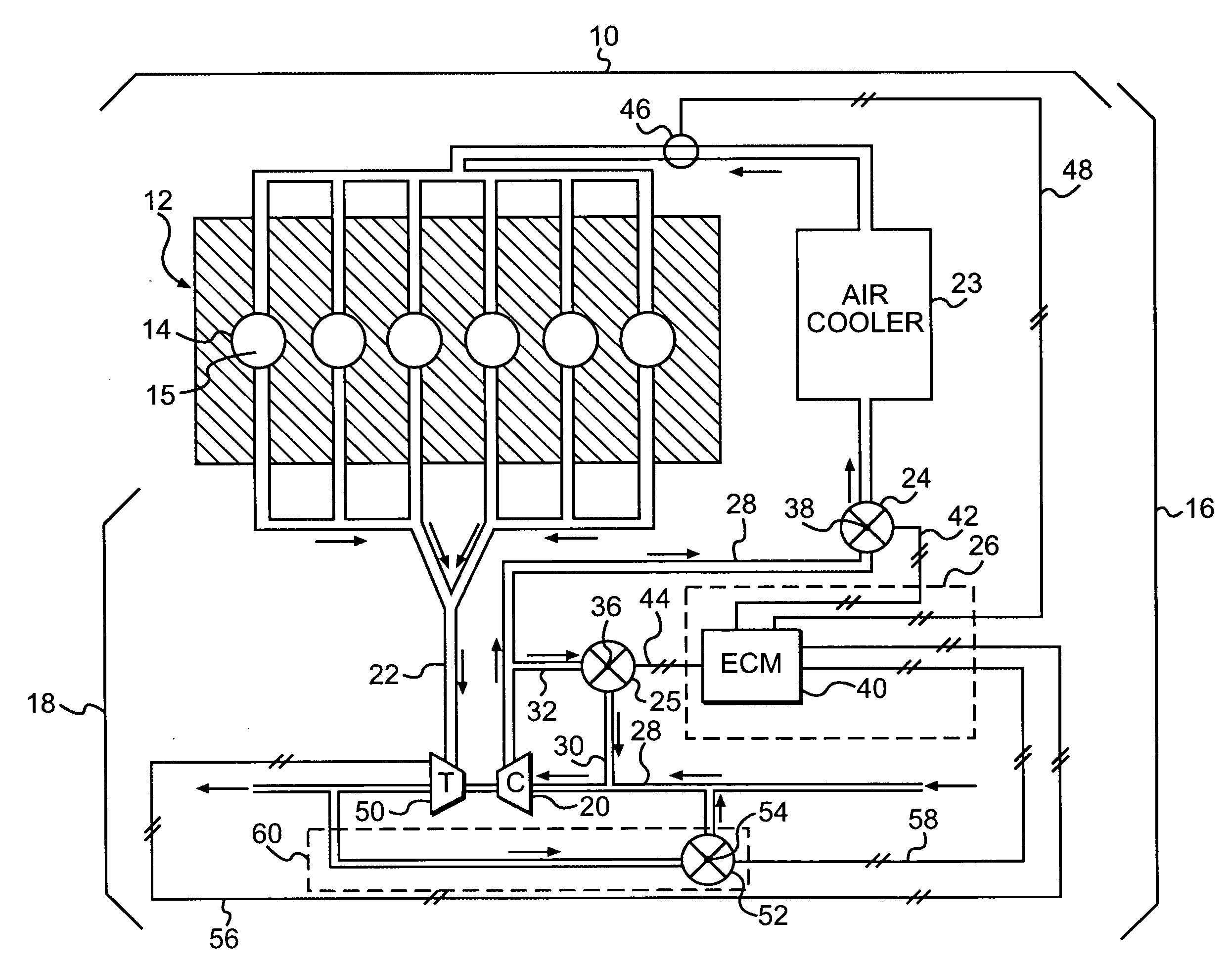
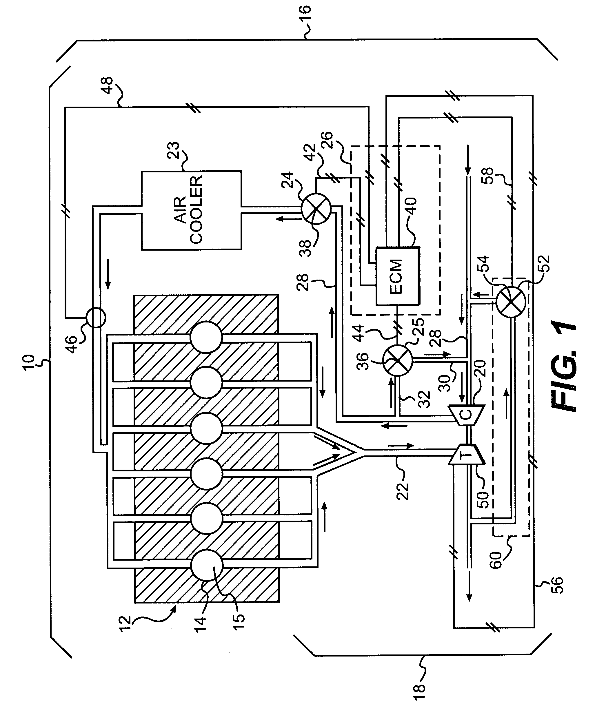
[0013]FIG. 1 illustrates an exemplary disclosed engine 10 having multiple components that cooperate to produce a power output. In particular, engine 10 may include an engine block 12 that defines a plurality of cylinders 14, a piston (not shown) slidably disposed within each cylinder 14, and a cylinder head (not shown) associated with each cylinder 14. The piston, cylinder head, and cylinder 14 may form a combustion chamber 15. In the illustrated embodiment, engine 10 includes six combustion chambers 15. However, it is contemplated that engine 10 may include a greater or lesser number of combustion chambers 15 and that the combustion chambers 15 may be disposed in an “in-line” configuration, a “V” configuration, or any other suitable configuration. For the purposes of this disclosure, engine 10 is depicted and described as a four-stroke gasoline engine. One skilled in the art will recognize, however, that engine 10 may embody any other type of internal combustion engine such as, for...


PUM


Abstract

A fluid control system for an engine is disclosed. The fluid control system may have a first fluid control component, a second fluid control component, and a controller in communication with the first and second fluid control components. The controller may be configured to determine an operational change associated with the first fluid control component to achieve desired operation of the engine. The controller may also be configured to determine an effect the operational change will have on performance of the second fluid control component, and adjust operation of the second fluid control component to accommodate the effect substantially simultaneously with implementation of the operational change.

Description

TECHNICAL FIELD[0001]The present disclosure relates generally to a control strategy and, more particularly, to a control strategy for decoupling interrelated air system components.BACKGROUND[0002]Internal combustion engines such as, for example, gasoline engines, diesel engines, and gaseous fuel powered engines, combust a mixture of air and fuel to produce a power output. The amount of air and fuel, and the ratio of air-to-fuel introduced into a combustion chamber of the engine can affect the power output, efficiency, and exhaust emissions of the engine. Typically, the amount of air introduced into the engine and the ratio of air-to-fuel is controlled by a number of different fluid handling components located in both the induction and exhaust systems of the engine.[0003]For example, a turbocharger includes a turbine, driven by exhaust from the engine, which directly drives a compressor to pressurize air directed into the engine. Depending on an internal geometry setting of the turbi...

Claims


Application Information

Patent Timeline
IPC IPC(8): G06F17/00
CPCF01N13/107F02B29/0425F02B29/0437F02B37/16F02B37/24F02D41/0007Y02T10/47F02D43/00F02D2041/1418F02D2041/1427F02M25/0709Y02T10/144Y02T10/42F02D41/0065F02M26/06Y02T10/12Y02T10/40
Inventor HU, GUANGDI
Owner CATERPILLAR INC
Why Eureka
Try Eureka