
Method of Producing Substrate for Thin Film Photoelectric Conversion Device, and Thin Film Photoelectric Conversion Device

Inactive Publication Date: 2008-09-04
KANEKA CORP
View PDF8 Cites 9 Cited by
  • Summary
  • Abstract
  • Description
  • Claims
  • Application Information

AI Technical Summary

Benefits of technology

[0014]According to the method of producing the substrate for the thin film photoelectric conversion device of the present invention, output properties of the thin film photoelectric conversion device fabricated using the substrate is improved because the etching with acid or alkali can remove steep protrusions, which cause decrease in Voc or FF, in a textured structure on a surface of the transparent conductive film mainly composed of zinc oxide and having a relatively large haze ratio causing a large optical confinement effect.

Problems solved by technology

In addition, since In is expensive, cost reduction of the film is also limited.
However, SnO2 is disadvantageously low in conductivity and in resistance to plasma.
When a zinc oxide film is formed by a sputtering method, however, fine unevenness (hereinafter referred to as texture) on a surface of the film is less likely formed and then optical confinement effect due to scattering of light in a thin film photoelectric conversion device including that film is lowered leading to decrease of electric power generation.
Therefore, when the zinc oxide film is formed by the sputtering method, it has been necessary to form surface unevenness by immersing and etching the film in an acid or alkali solution.

Method used


Image

  • Method of Producing Substrate for Thin Film Photoelectric Conversion Device, and Thin Film Photoelectric Conversion Device
  • Method of Producing Substrate for Thin Film Photoelectric Conversion Device, and Thin Film Photoelectric Conversion Device
  • Method of Producing Substrate for Thin Film Photoelectric Conversion Device, and Thin Film Photoelectric Conversion Device

Examples


example 1

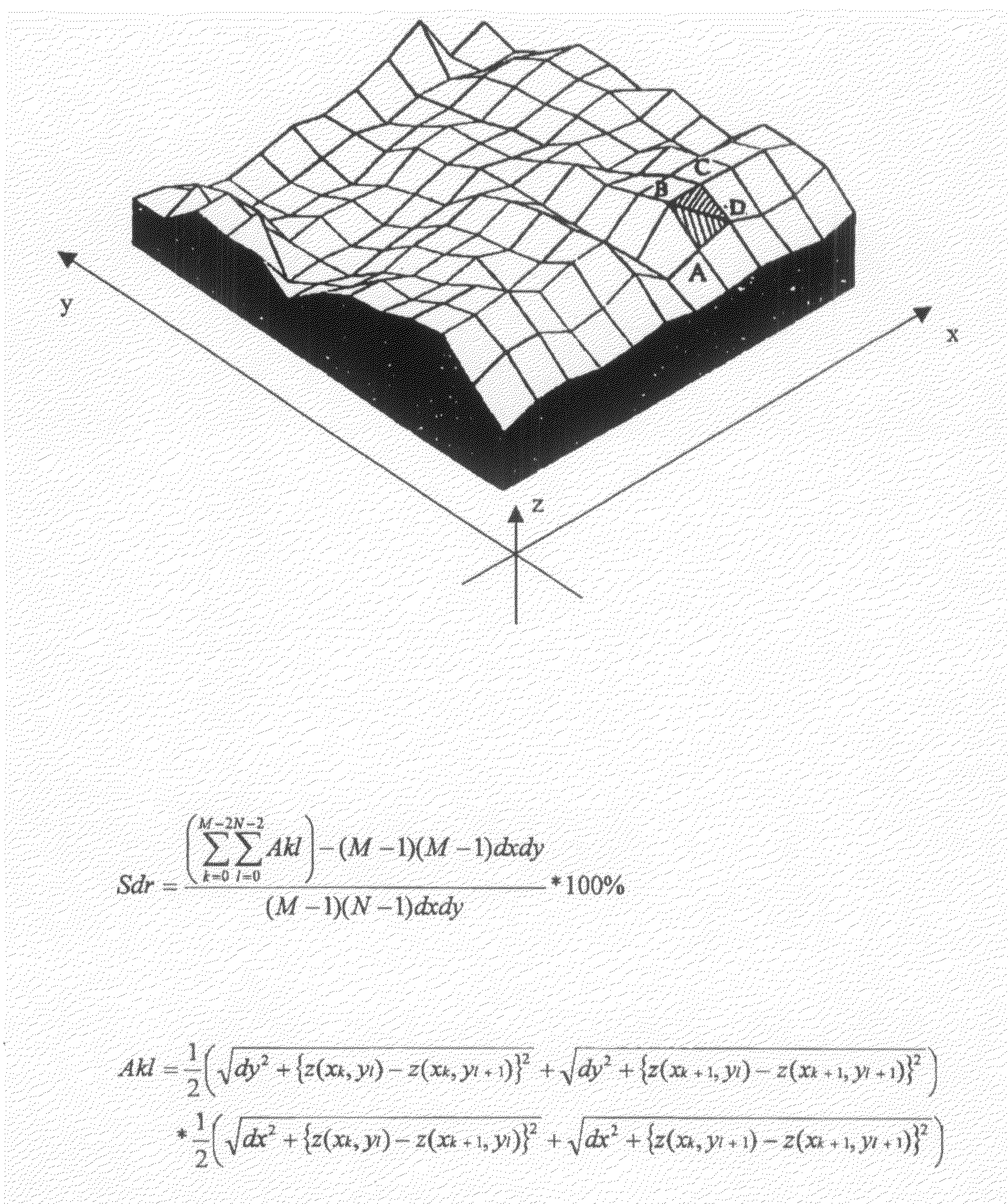
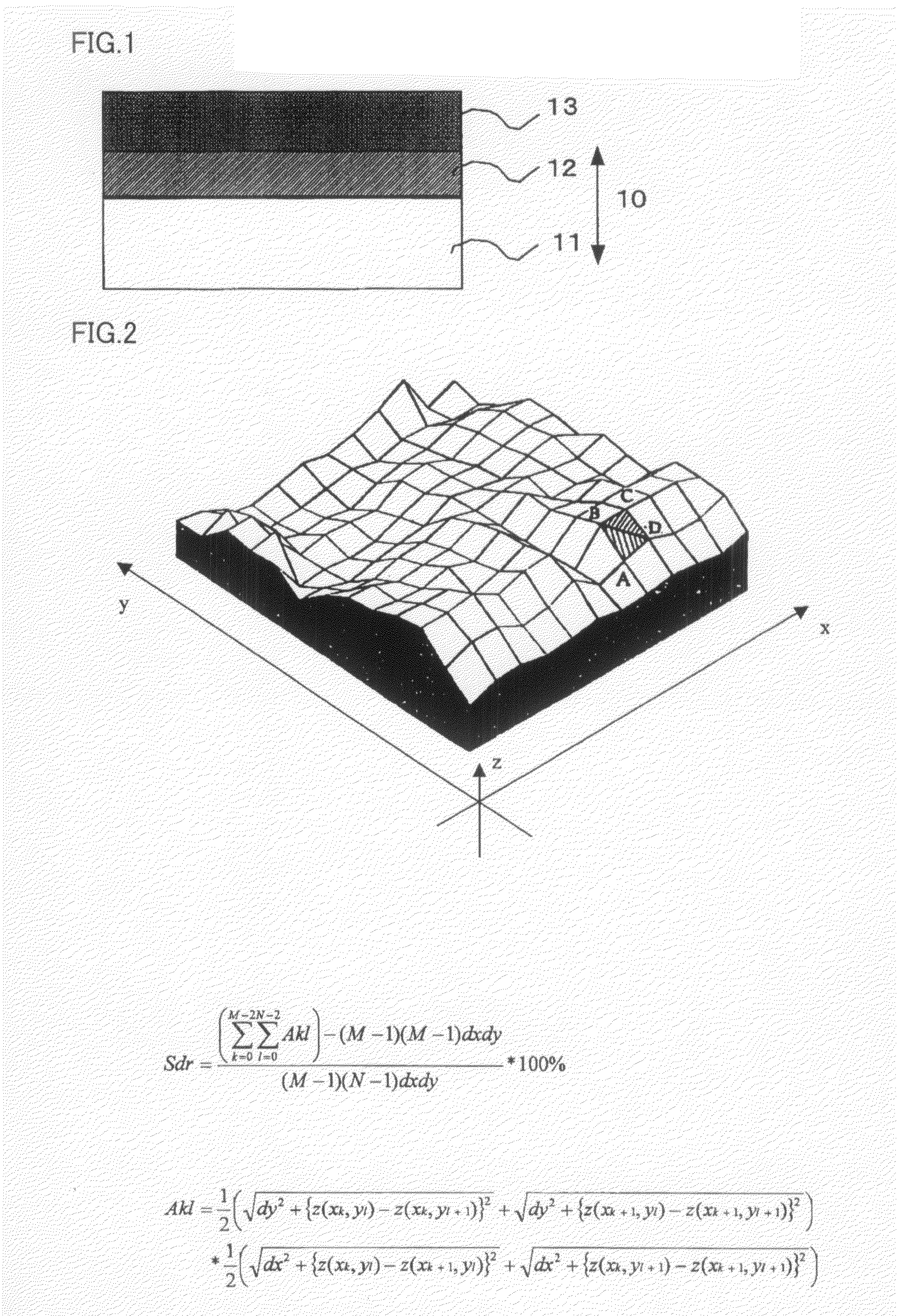
[0051]Initially, zinc oxide film 13 was formed as the transparent conductive film on transparent insulator base 10 that includes transparent ground base 11 of a glass plate and insulating underlayer 12 of SiO2 formed thereon, and its SDR and haze ratio were measured.

[0052]Specifically, transparent insulator base 10 was initially loaded in a film-forming chamber, and then hydrogen and diborane were introduced at 1500 sccm and 500 sccm into the chamber respectively and the insulator base was held for 30 minutes at a deposition temperature of 150° C. Successively, the zinc oxide film was deposited to 1.5 μm thickness under conditions in which vaporized water and diethyl zinc were introduced at 900 sccm and 800 sccm respectively and the pressure in the film-forming chamber was held at 45 Pa. The film thickness was measured with an ellipsometer. The SDR was measured with the AFM and found as 67, while the haze ratio was measured with the haze meter and found as 18%.

[0053]Thereafter, the ...

examples 2 to 5

[0058]Zinc oxide layer 13 deposited on transparent insulator base 10 by the same method as in Example 1 was treated with 1 vol % acetic acid aqueous solution. Here, the time for treatment, which was set to 5 seconds in Example 1, was varied in a range from 10 to 40 seconds. Specifically, the time for treatment with 1 vol % acetic acid aqueous solution was set to 10 seconds in Example 2, 20 seconds in Example 3, 30 seconds in Example 4, and 40 seconds in Example 5. The thin film photoelectric conversion device fabricated on the substrate in each embodiment as above was irradiated with AM 1.5 spectrum at energy density of 100 mW / cm2 and its output properties were measured at a temperature of 25° C. The results are shown in Tables 1, 2 and 3, together with results in Example 1 and Comparative Example 1. Here, Table 1 shows the relation between the time for treatment and variation in the SDR, Table 2 shows the relation between the time for treatment and variation in the haze ratio, and ...


PUM


Abstract

This invention provides a method of producing a substrate for a thin film photoelectric conversion device, the substrate being able to make it possible to fabricate the thin film photoelectric conversion device free from lowering in its open-circuit voltage or its fill factor even when the substrate includes a transparent conductive film that is mainly composed of zinc oxide and has a relatively large haze ratio for causing a large optical confinement effect. The method of producing the substrate for the thin film photoelectric conversion device according to the present invention is characterized in that a transparent conductive film formed on a transparent insulator base, which is mainly composed of zinc oxide and having a haze ratio of at least 5%, is etched with an acid or alkali solution. Output properties of the thin film photoelectric conversion device fabricated using the substrate is improved because the etching with acid or alkali can remove steep protrusions, which cause decrease in Voc or FF, in a textured structure on a surface of the film.

Description

TECHNICAL FIELD[0001]The present invention relates to a method of producing a substrate having high transmittance, low electric resistance and an excellent surface shape to be used for a thin film photoelectric conversion device, and relates to a thin film photoelectric conversion device fabricated with the substrate.BACKGROUND ART[0002]In recent years, importance of a transparent conductive film has increasingly been rising. The transparent conductive film is used as a material for a transparent electrode in each of various light receiving devices such as a thin film photoelectric conversion device typified by a solar cell or of display devices of liquid crystal, PDP, EL, and the like. In particular, the transparent conductive film for a thin film photoelectric conversion device should have high transparency, high electric conductivity, and surface unevenness for effective use of light. As the transparent conductive film, there are now known films of indium oxide (In2O3) to which a...

Claims


Application Information

Patent Timeline
IPC IPC(8): H01L31/00
CPCH01L31/0745H01L31/077Y02E10/50H01L31/1884H01L31/18H01L31/022483H01L31/02366H01L31/075Y02E10/548
Inventor MEGURO, TOMOMIYAMAMOTO, KENJI
Owner KANEKA CORP
Learn More