Stepping motor

a stepping motor and motor shaft technology, applied in the direction of dynamo-electric machines, instruments, clocks, etc., can solve the problems of increased ripple ripple and revolution speed ripple of the motor, drawbacks of vibration and noise, and increase production costs. , to achieve the effect of reducing detent torque, reducing size, and increasing torqu

Inactive Publication Date: 2008-09-04
MITSUMI ELECTRIC CO LTD
View PDF9 Cites 26 Cited by
  • Summary
  • Abstract
  • Description
  • Claims
  • Application Information

AI Technical Summary

Benefits of technology

[0007]In addition, in recent years, in conjunction with emergence of demands for higher performances on various types of equipment, there has emerged a demand for stepping motors with a low detent torque. In the case of a stepping motor having a large detent torque, the torque ripple and revolution speed ripple of the motor are increased, producing drawbacks of vibration and noise. In addition, when the stepping motor is used as a positioning motor, the positioning accuracy is decreased.
[0008]An object of the invention is to provide a stepping motor, which is small in size and which can increase the torque and decrease the detent torque while maintaining the low production costs.
[0010]According to the configuration described above, by forming the stator yoke element of the sheet of silicon steel which is substantially 0.7 mm thick, the torque can be increased and the detent torque can be decreased compared to the conventional stepping motor in which the stator yoke element is formed of the sheet of silicone steel which is 0.5 mm thick.
[0011]In the stepping motor according to the aspect of the invention, since the stator yoke element is formed of the sheet of silicone steel which is substantially 0.7 mm thick, a reduction in size and an increase in torque can be attained without increasing the production costs. In addition, a reduction in detent torque can be attained, so as to reduce the vibration and noise of the motor.

Problems solved by technology

However, in the event that the amount of windings of the exiting coils of a stepping motor is increased, the miniaturization of the stepping motor is interrupted, and in the event that the quality level of a material for a permanent magnet is increased, the production costs are increased considerably.
In the case of a stepping motor having a large detent torque, the torque ripple and revolution speed ripple of the motor are increased, producing drawbacks of vibration and noise.
In addition, when the stepping motor is used as a positioning motor, the positioning accuracy is decreased.

Method used


Image

  • Stepping motor
  • Stepping motor
  • Stepping motor

Examples


Embodiment Construction

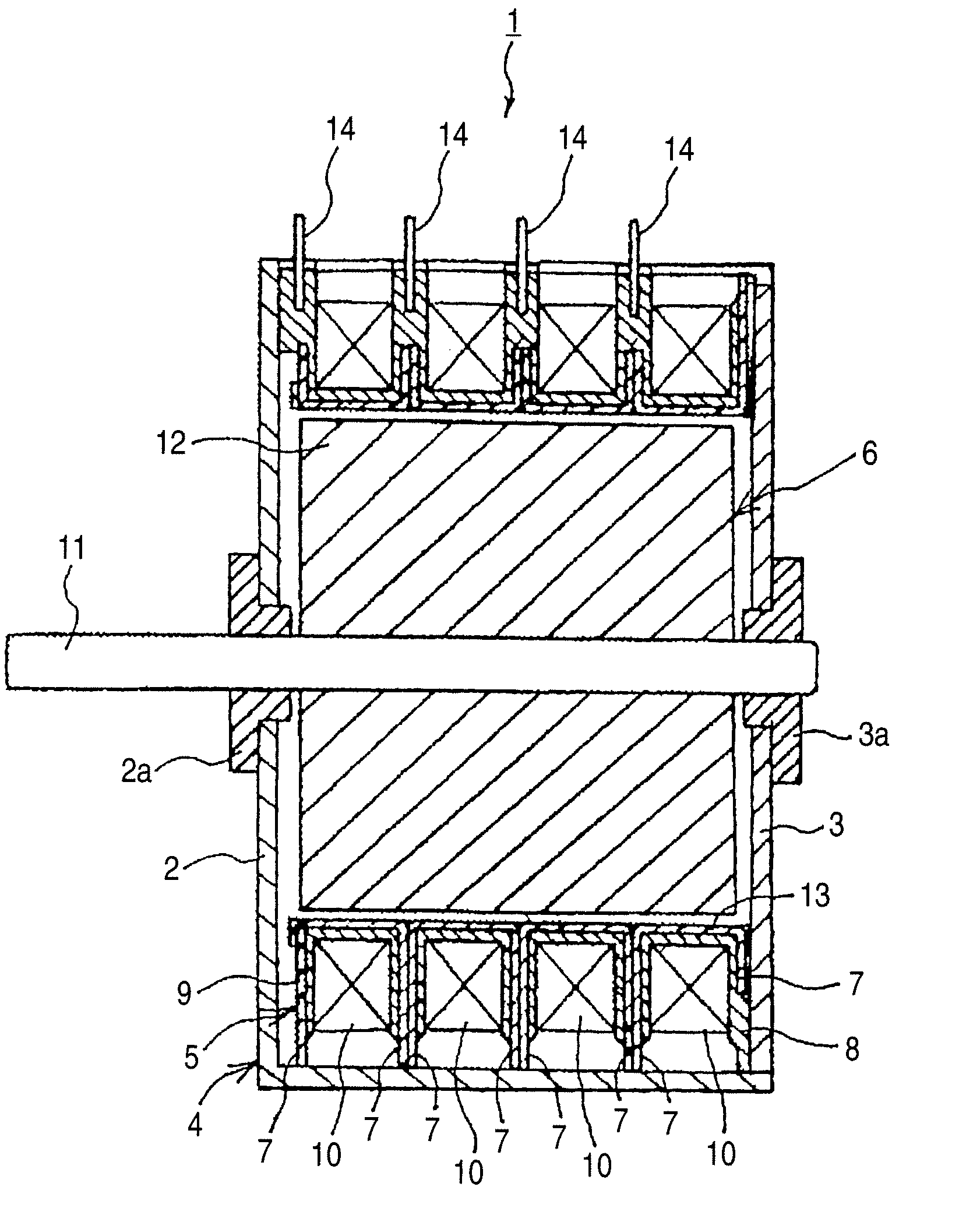
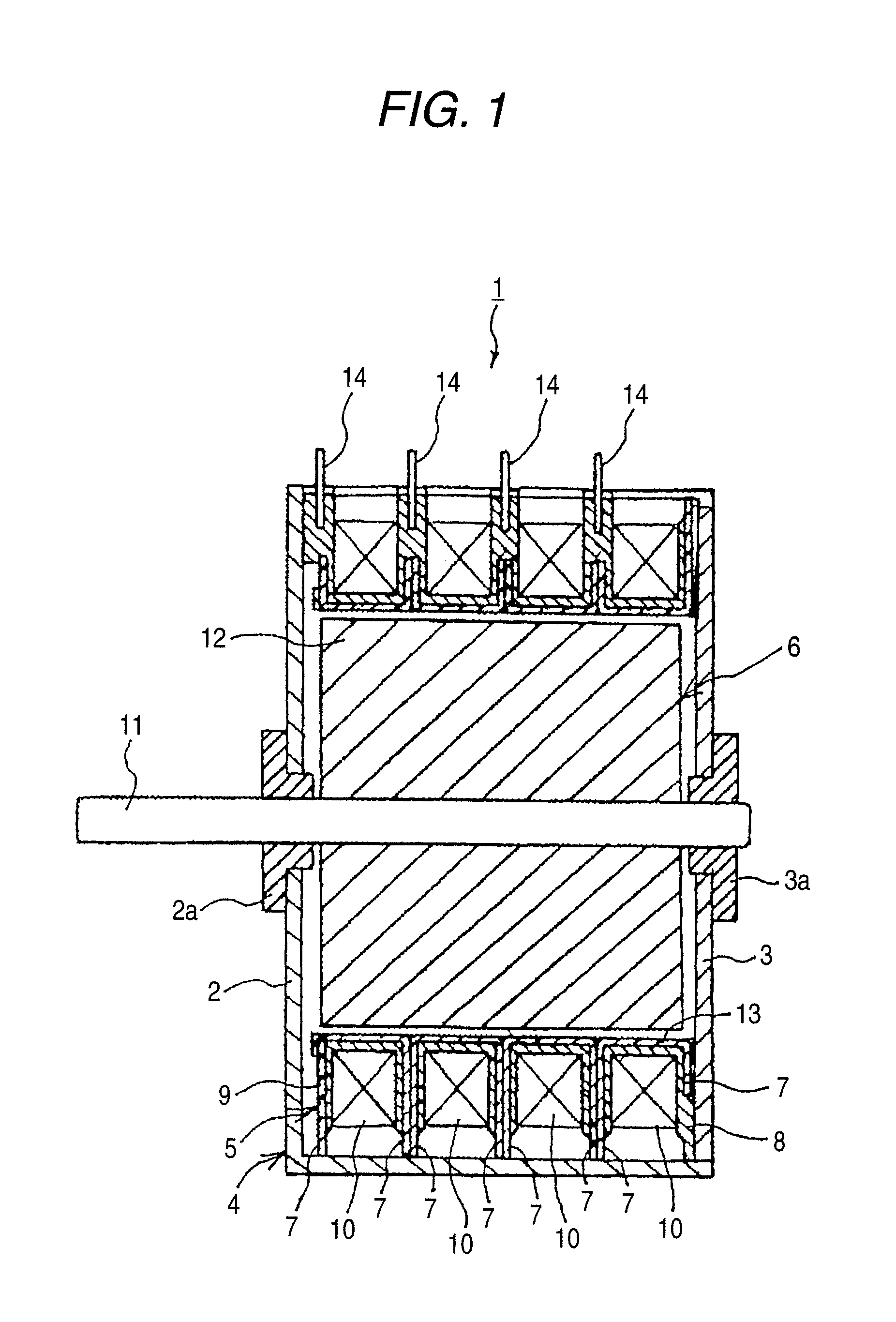
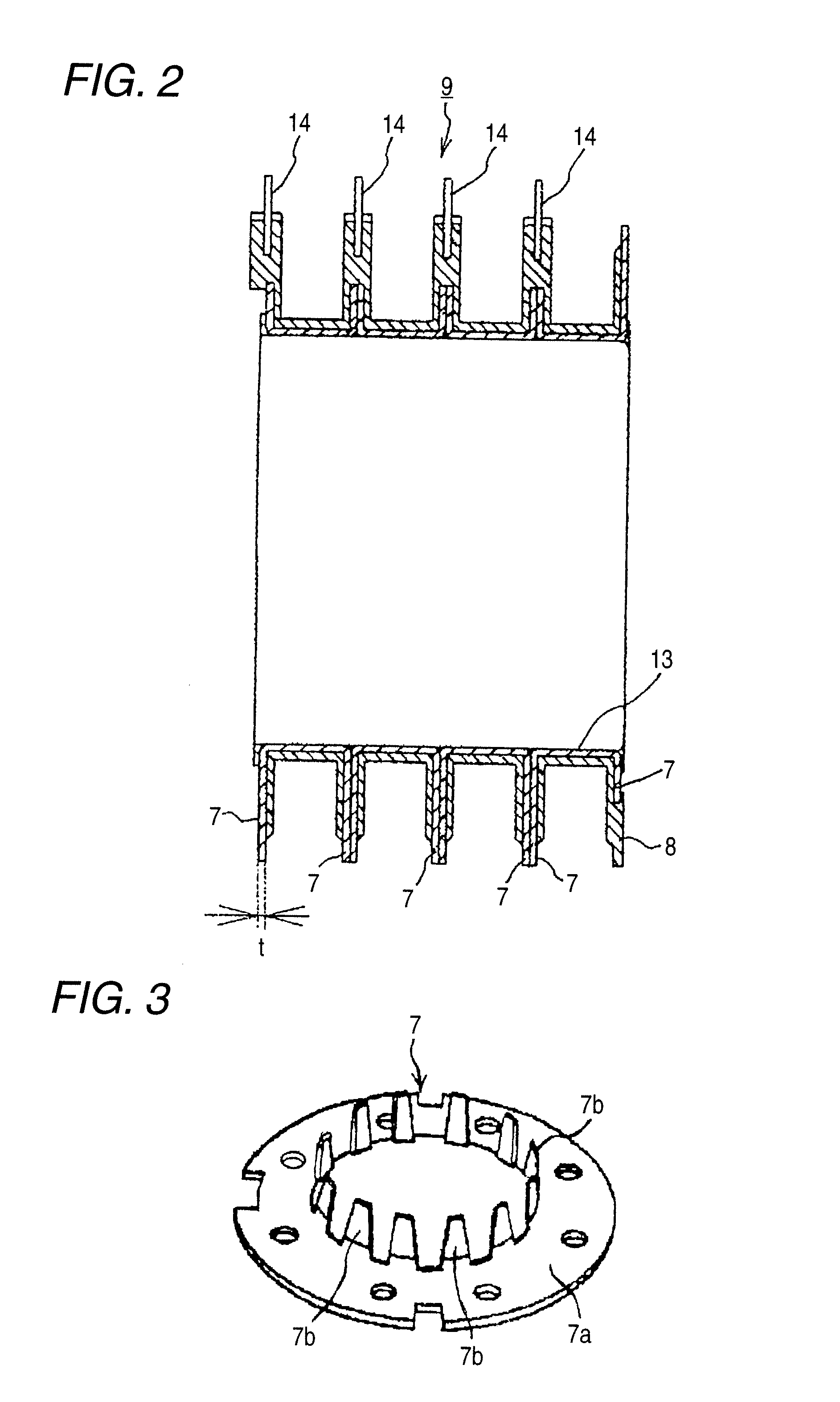
[0022]The object to realize a stepping motor which is small in size and which can increase the torque and decrease the detent torque while maintaining the low production costs realized is attained by realizing a stepping motor including a rotor element made up of a permanent magnet which is magnetized to a multiplicity of poles, a stator yoke element provided in such a manner as to face the rotor element concentrically and having a plurality of comb tooth-like pole portions, exciting coils mounted on outer circumferential portions of the comb tooth-like pole portions and a case yoke element encompassing the exiting coils and the stator yoke element, wherein the stator yoke element is made of a sheet of silicon steel whose thickness is substantially 0.7 mm.

[0023]Hereinafter, an embodiment of the invention will be described based on FIG. 1. In FIG. 1, a stepping motor 1 is made up of a case yoke element 4 which is made up, in turn, of a hollow cylindrical case 2 which is opened at one...


PUM


Abstract

A rotor rotable about a rotary axis is magnetized so as to have a plurality of poles along a circumferential direction thereof. Stator yokes each of which has a plurality of pole portions facing an outer circumferential face of the rotor is provided. An exciting coil is wound on the pole portions. Each of the stator yokes is made of a sheet of silicon steel having a thickness of 0.7 mm.

Description

BACKGROUND OF THE INVENTION[0001]1. Field of the Invention[0002]The present invention relates to a stepping motor, and more particularly to a stepping motor which can increase torque and decrease detent torque.[0003]2. Description of the Related Art[0004]For example, Japanese Patent Application No. 2005-110377A discloses a stepping motor which includes a rotor element made up of a permanent magnet which is magnetized to a multiplicity of poles, a stator yoke element provided in such a manner as to face the rotor element concentrically and having a plurality of comb tooth-like pole portions, exciting coils mounted on outer circumferential portions of the comb tooth-like pole portions and a case yoke element encompassing the exiting coils and the stator yoke element.[0005]In addition, many of stator yokes of recent stepping motors are made by a pressed sheet of silicon steel and are manufactured using sheets of silicon steel which are normally 0.5 mm thick.SUMMARY OF THE INVENTION[000...

Claims


Application Information

Patent Timeline
Patent Type & Authority Applications(United States)
IPC IPC(8): H02K37/00
CPCH02K37/14H02K1/145
Inventor SAKAMOTO, TAKANORIIMAMURA, YUKI
Owner MITSUMI ELECTRIC CO LTD
Why Eureka
Try Eureka