Remote control lighting assembly and use thereof

Active Publication Date: 2008-09-04
HONG KONG APPLIED SCI & TECH RES INST
View PDF1 Cites 27 Cited by
  • Summary
  • Abstract
  • Description
  • Claims
  • Application Information

AI Technical Summary

Benefits of technology

[0039]The first, second and at least one further substrates are preferably substantially parallel to each other and overlapping each other. Preferably the first, second and at least one further substrates are axially aligned and progressively distally smaller in size. The at least a first, second and further light emission sources are prefe

Problems solved by technology

However, most lighting devices using infrared signals for remote control purpose may unavoidably suffer the drawback of less flexibility including the directional nature of the infrared signals.
Further, most lighting devices using radio frequency signals may be unnecessar

Method used


Image

  • Remote control lighting assembly and use thereof
  • Remote control lighting assembly and use thereof
  • Remote control lighting assembly and use thereof

Examples


Example

[0052]While the present invention has been explained by reference to the examples or preferred embodiments described above, it will be appreciated that those are examples to assist understanding of the present invention and are not meant to be restrictive. Variations or modifications which are obvious or trivial to persons skilled in the art, as well as improvements made thereon, should be considered as equivalents of this invention.

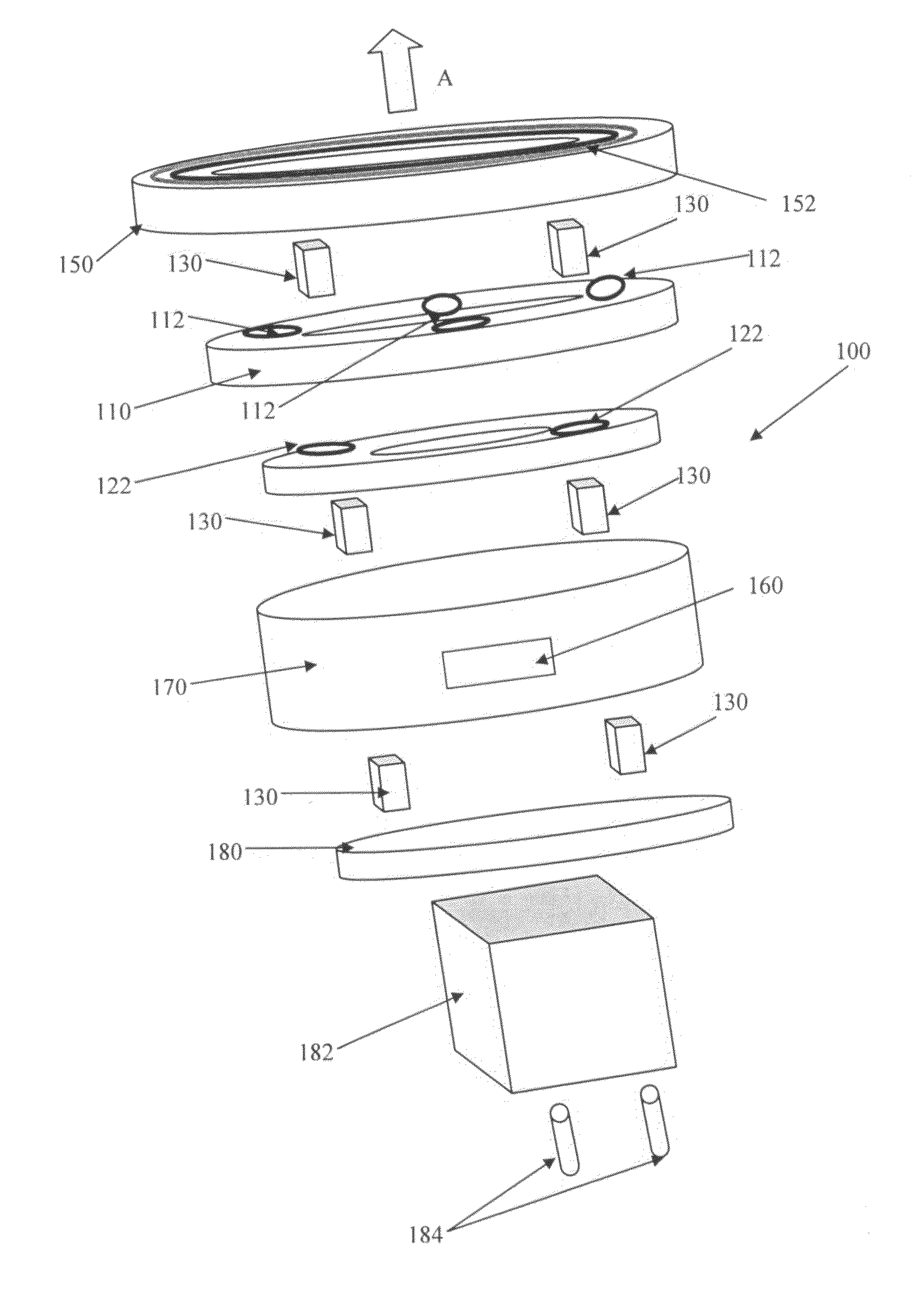
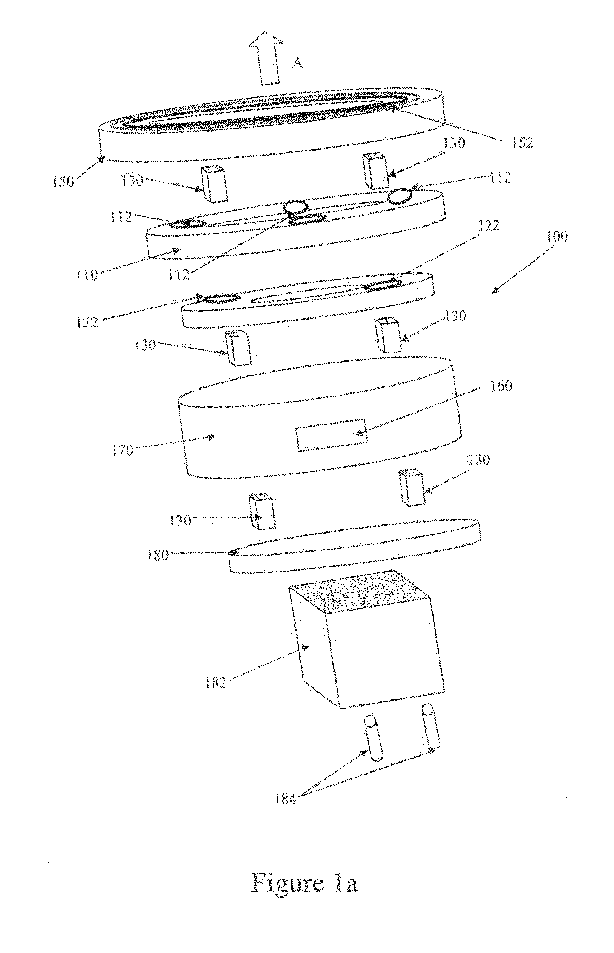
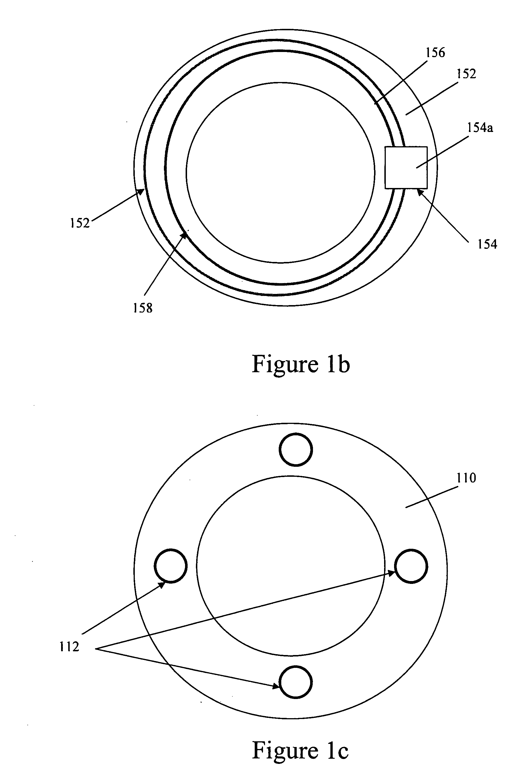
[0053]Referring to FIGS. 1a, 1b, 1c, 1d and 1e, there is shown an exemplary embodiment of a lighting device 100 according to the present invention. The lighting device comprises a first substrate 110 and a second substrate 120. The first substrate 110 carries a plurality of light emission sources, in the present embodiment a plurality of LEDs 112, and the second substrate carries a second plurality of light emission sources, in the present embodiment also a plurality of LEDs 122. The substrates 110, 120 are provided in an overlapping manner and are maint...


PUM


Abstract

A remote-controllable lighting device comprising a first substrate and an adjacent second substrate maintained in a spaced apart relationship to allow airflow therebetween and at least partly overlapping each other, at least the second substrates carrying thereon at least one emission sources, the first substrate being located towards a proximal end of the device and the second substrate being located towards a distal end of the device; said first substrate being arranged so as to allow light generated by the at least one located second light emission source to pass thereby in a direction defining a primary light emission direction and said first light emission source located so as to emit light in said primary light emission direction; said first and second substrate being in thermal communication so as to allow heat generated by the at least one light emission sources to flow between the substrates so as to provide thermal distribution between the substrates, the first and second substrate being formed of a thermally conductive material suitable for convection of the generated heat therefrom; a signal detector for receiving a wirelessly transmitted control signal from a remote control device; said signal receiver being located proximal of the first substrate in the primary light emission direction; and a controller in communication with said signal detector and the light emission sources and for controlling at least one characteristic of at least one light emission source responsive to said control signal.

Description

FIELD OF THE INVENTION[0001]The present invention relates to a lighting device, more particularly to a lighting device having wireless remote control.BACKGROUND OF THE INVENTION[0002]A lighting device, for example a light bulb or assembly, is conventionally controlled by a switch electrically connected to the light device. In recent developments, wireless communication mechanisms such as infrared signals and radio frequency signals have been used for control of the lighting device.[0003]However, most lighting devices using infrared signals for remote control purpose may unavoidably suffer the drawback of less flexibility including the directional nature of the infrared signals. Further, most lighting devices using radio frequency signals may be unnecessarily bulky.[0004]Furthermore, conventional lighting devices may only support remote control activation over a relatively short distance which heavily depends upon the remote control signal. This may not be convenient especially in a ...

Claims


Application Information

Patent Timeline
IPC IPC(8): H01J7/24
CPCF21K9/00F21V23/0435F21V23/0442H05B33/0857F21Y2101/02H05B33/0803F21V29/02F21Y2115/10H05B45/20H05B45/00F21V29/503F21V29/89F21V29/86
Inventor ZHANG, ZHIKUANLU, MINGLEUNG, LYDIALL, KELVINWU, ENBOA
Owner HONG KONG APPLIED SCI & TECH RES INST
Why Eureka
Try Eureka